Two KF flanges
Matching flange faces provide the quick-connect interface on both sides of the joint.

A standard KF joint uses two matching flange faces, a centering ring, an O-ring and a clamp. The modular connection supports straightforward assembly, inspection and reconfiguration, while the selected tube outside diameter, material and seal must still match the application.
Matching flange faces provide the quick-connect interface on both sides of the joint.
The ring aligns the seal and keeps it positioned between the mating flange faces.
The elastomer is compressed between the flange faces to form the vacuum seal.
The clamp applies closing force around the angled outer surfaces of the flanges.
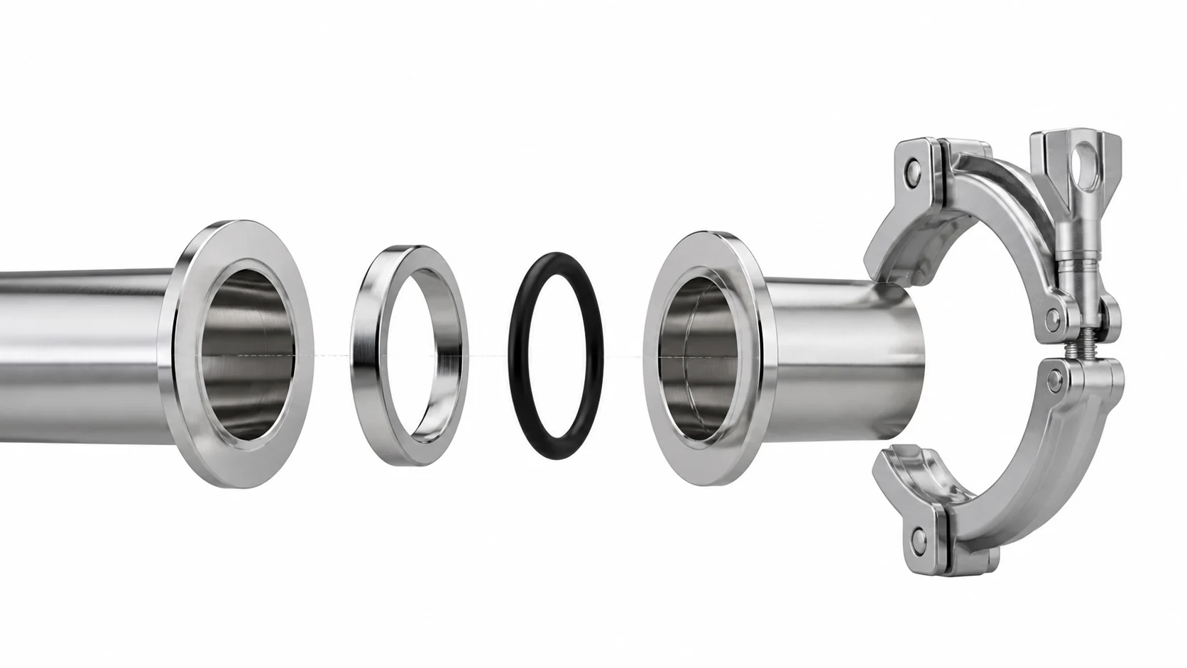
The illustration explains component relationships only. Final geometry, material and acceptance requirements are defined by the selected product drawing and order specification.
Compatibility reminder: KF flange designation and tube outside diameter are related but not always identical. Confirm both dimensions before ordering replacement or mixed-origin components.
Buyers and equipment manuals may use different names for the same quick-clamp connection family. A name match does not replace dimensional confirmation, especially when components come from different manufacturers or regional tube systems.
Common abbreviation for Klein Flange and the primary term used throughout this product category.
A widely used designation associated with nominal diameter, frequently seen in pump and instrument port descriptions.
Quick Flange terminology used by some suppliers to describe the same general quick-clamp connection style.
For replacement parts: send the existing component marking, flange outside diameter, tube outside diameter and a clear photo. RUIJIA can then review the requested interface against the available product configuration.
Use the category pages below to review the specific component types available for sealing, routing, straight connections, movement compensation and joint clamping.

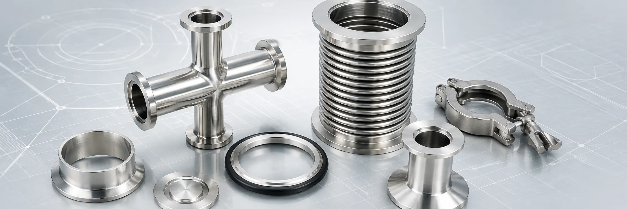
KF Centering Rings are the core positioning and sealing components for ISO-KF standard quick-release vacuum flanges, and an indispensable basic part for fast and reliable connection of small and medium-sized vacuum piping systems.

KF Flange and Fittings is refers to the KF series of vacuum components, a series of standardized connecting parts for vacuum systems,includes KF Centering Rings, KF Vacuum Flanges,KF Vacuum Fittings,KF Vacuum Bellows, KF Nipples and KF Clamps.
The typical KF or NW assembly consists of two identical flanges, a center-ring, and an aluminum clamp with a wingnut fastener frequently connect and disconnect without tools.

KF Vacuum Fittings is a series of connecting parts used in vacuum systems, usually including elbows, tees, crosses, etc., using the clamp connection.A wide range of flange sizes from KF10 to KF50 to meet the needs of vacuum pipe connections of different diameters.

KF Vacuum Bellows is a high-quality flexible connecting pipe for modern industrial piping. We can provide bendable and compressible bellows in sizes from KF10 to KF50 in customized lengths of 100mm, 200mm, 300mm, 500mm, 1000mm and so on.

KF Nipples are basic and essential connecting components for ISO-KF quick-release vacuum systems, used to connect vacuum chambers, tubes, valves, pumps and other vacuum equipment to form a complete straight vacuum pipeline.

KF Clamp is usually made of stainless steel 304, 316L or aluminum. It is used to tightly connect two butted KF flanges by wrapping around the flanges and utilizing the clamp's fastening device (e.g., butterfly nut, etc.) to create a tightening force.
Not sure which component fits your assembly?
Send the KF size, tube outside diameter and connection requirement for technical review.
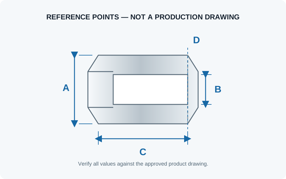
KF size names describe the connection family, but the welded tube outside diameter can vary with the selected component and regional tubing convention. Do not select a flange, nipple or fitting from the nominal name alone.
| Dimension or specification | Why it matters | What to send | Verification source |
|---|---|---|---|
| KF / NW designation | Identifies the mating flange family and sealing assembly | Existing marking or required connection size | Selected product drawing |
| Flange outside diameter | Helps confirm clamp and centering-ring compatibility | Measured outside diameter in mm | Approved dimensional drawing |
| Tube outside diameter | Controls welding fit and line compatibility | Actual tube OD and wall thickness | Tube specification and fitting drawing |
| Overall or centerline length | Affects equipment spacing and system layout | Required length or marked-up sketch | Order drawing |
| Port orientation | Prevents installation conflicts on elbows, tees and crosses | Orientation sketch or 3D model reference | Approved fabrication drawing |
Use reference values for preliminary selection only: the following catalog data helps identify likely interfaces, but the selected product drawing and current quotation remain the final dimensional reference.
The KF designation identifies the mating flange family. It does not always identify the welded tube outside diameter. The reference range below supports preliminary comparison across common catalog configurations.
| KF designation | Reference flange OD | Examples shown in the catalog | Confirm before ordering |
|---|---|---|---|
| KF10 / KF16 | 30 mm | Blanks, weld flanges, nipples, clamps and centering rings | Tube OD, bore and sealing assembly |
| KF25 | 40 mm | Flanges, nipples, flexible hoses, elbows, tees and crosses | Regional tube convention and overall length |
| KF40 | 55 mm | Flanges, fittings, bellows, clamps and centering rings | Tube OD, material, seal and centerline dimensions |
| KF50 | 75 mm | Flanges, fittings, bellows, clamps and centering rings | Tube OD, material, seal and installation space |
| KF63 | 87 mm | Blanks, socket-weld flanges and chain clamps | Product type and actual mating dimensions |
| KF80 | 114 mm | Blanks, socket-weld flanges and chain clamps | Clamp type, bore and assembly dimensions |
| KF100 | 134 mm | Blanks, socket-weld flanges and chain clamps | Clamp type, bore and assembly dimensions |
| KF160 | 190 mm | Blanks, socket-weld flanges and chain clamps | Current drawing and component availability |
Reference flange outside diameters are taken from the supplied KF catalog. Product availability and dimensions can vary by component family and revision.
| KF size | U.S. tube OD examples | European tube OD examples | Japan / JIS examples |
|---|---|---|---|
| KF10 | 12.7 mm | 14 mm | Confirm requested tube specification |
| KF16 | 19.05 mm | 20 mm | Confirm requested tube specification |
| KF25 | 25.4 mm | 28 mm | 27.2 mm or JIS pipe variants |
| KF40 | 38.1 mm | 45 mm | 42.7 mm or JIS pipe variants |
| KF50 | 50.8 mm | 57 mm | 60.5 mm catalog variant |
Compatibility check: send the existing flange marking, measured flange OD, actual tube OD and a clear photograph. Do not assume that two KF parts use the same weld tube simply because their nominal flange designation matches.
Material and seal selection affects temperature capability, chemical compatibility, cleanliness and maintenance. The catalog identifies the configurations below; final suitability must be reviewed against the actual medium and operating conditions.
For technical review: provide the process medium, operating temperature, cleaning method and requested material documentation together with the KF size.
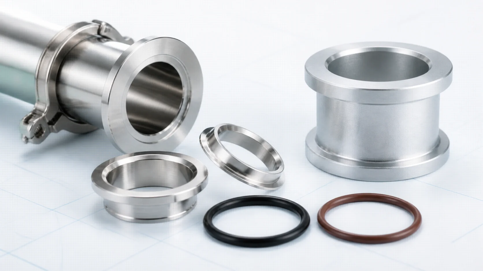
The catalog lists 304 stainless steel for most flanges, nipples, fittings, hoses, bellows and centering rings.
Aluminum versions are shown for selected blanks, clamps, nipples, elbows, tees and centering rings. Some outer-ring assemblies list a 316 stainless-steel option.
The catalog lists Viton and NBR for centering-ring sealing assemblies.
Temperature references are not system ratings: actual seal life and suitability depend on gas or chemical exposure, pressure, duration, compression, cleaning method and installation condition.
Select the product type first, then confirm interface dimensions, operating conditions, material, seal and installation requirements.
| Visual | Requirement | Typical component | Details to confirm | Next step |
|---|---|---|---|---|
|
Seal two matching flange faces | Centering ring, O-ring and clamp | KF size, seal material, clamp construction | Review centering rings |
 |
Add a quick-connect end | KF flange | Tube OD, weld end, material, flange dimensions | Review KF flanges |
|
Change direction or create a branch | Elbow, tee or cross | Port sizes, angle, orientation, centerline dimensions | Review KF fittings |
|
Connect two points in a straight run | KF nipple | Overall length, tube OD, wall thickness, material | Review KF nipples |
|
Accommodate movement or alignment | KF bellows | Free length, motion, cycle conditions, installation alignment | Review KF bellows |
|
Transition to another interface | Vacuum adapter | Both end standards, sizes, seal types and materials | Review vacuum adapters |
|
Close a routine service joint | Wing-nut or standard quick clamp | KF size, clamp material, access for tightening | Review routine clamps |
|
Support repeated opening or locking | Spring or toggle clamp | KF size, release method, lock requirement | Compare clamp options |
|
Connect a larger or mounted interface | Chain or bulkhead clamp | Flange size, mounting surface, bolt pattern and access | Review mounting hardware |
|
Add a flexible line section | Flexible hose, braided hose or bellows | Length, motion, alignment, cycle and installation conditions | Review flexible sections |
Confirm flange size, tube OD and both mating ends.
Define pressure, temperature, media and cleanliness.
Select construction and O-ring for the operating conditions.
Agree drawings, inspection, testing and documentation.
Accessible connections for compatible pumps, gauges and traps.
Modular routing for experimental and teaching systems.
Auxiliary lines between chambers, valves and hardware.
Standard interfaces with reviewed lengths and port layouts.
The connection family should be selected at system level. Port size, vacuum conditions, assembly method, temperature and maintenance access all influence the decision.
| Connection family | Joint method | Useful selection context | Category |
|---|---|---|---|
| KF / NW | Clamp with centering ring and elastomer O-ring | Compact, modular lines where convenient assembly and service access are important | KF components |
| ISO | Centering ring and O-ring secured by clamps, claws or bolts according to flange style | Larger nominal line sizes and system layouts using ISO vacuum interfaces | ISO components |
| CF | Bolted metal-gasket joint with mating knife edges | Applications that require an all-metal sealed connection and compatible operating conditions | CF components |
These connection families are not directly interchangeable. Use a purpose-designed adapter and verify both sealing systems when moving between standards.
RUIJIA presents CNC machining, vacuum welding, heat treatment, helium mass-spectrometer leak detection and material-analysis equipment among its production and inspection capabilities. The applicable process, acceptance criteria and documentation should be confirmed for each quoted item.
Define the dimensions and tolerances that matter to mating, installation and system layout. A drawing is recommended for non-standard parts.
Specify the required stainless-steel grade, aluminum component or seal compound, together with any requested material documentation.
State the test method, acceptance criterion, test condition and report requirement instead of relying on a general sealing claim.
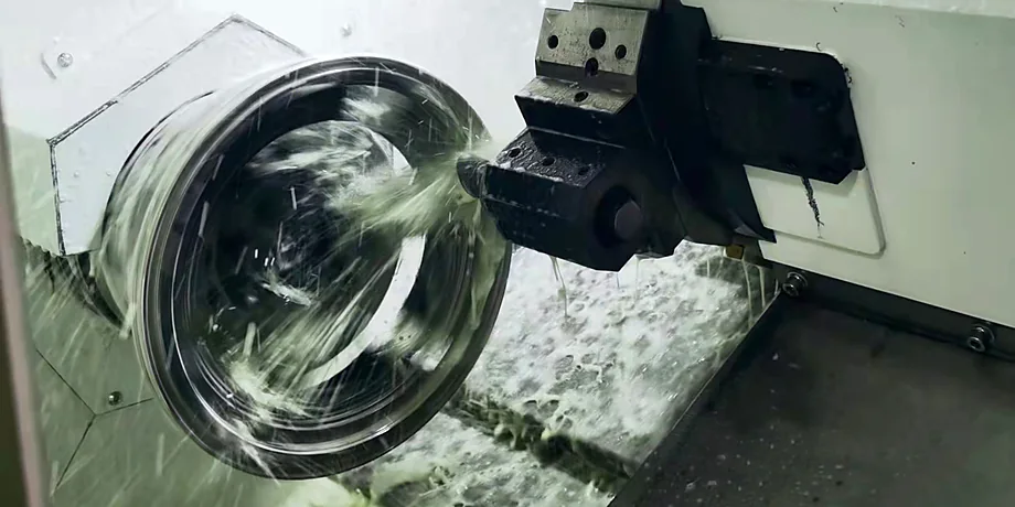
CNC machining supports the dimensional features required for flange faces, fitting bodies and reviewed custom components.
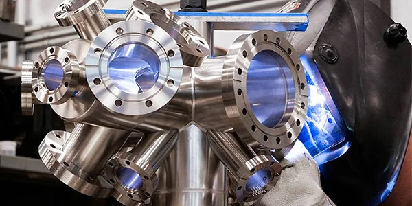
Welding activities are reviewed against the applicable component drawing and order requirements before dimensional verification.
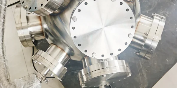
Confirm the assembled condition, test method, test conditions, acceptance criteria and reporting requirements for the quoted item.
A complete enquiry reduces avoidable clarification and helps the supplier check interface compatibility before quoting.
Use these engineering guides to continue from component selection into movement, interface transitions and system isolation.
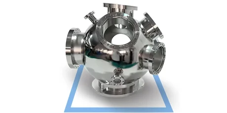
Review how alignment, movement and installed length affect the way a bellows section is specified.
Read the guide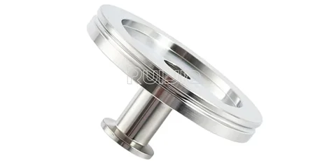
Compare both connection ends, nominal sizes, sealing methods and materials before defining a transition.
Read the guide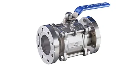
Identify the valve function, connection standard, operating conditions and actuation needs for the system.
Read the guide
Rich stock, fast delivery
Quick response within 24h
Quality assurance
Accessory replacement
GET A QUOTE