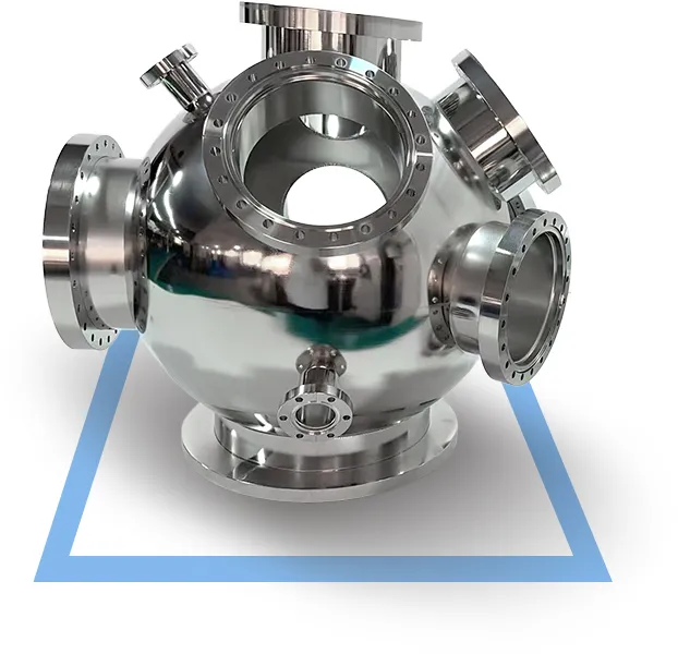
Large vacuum flange leaks often trace back to torque, O-ring condition, or sealing surface damage. Learn a systematic troubleshooting approach.




KF vacuum bellows are flexible connectors used in vacuum systems to accommodate movement, absorb vibration, and compensate for misalignment between components. The “compression” in compressible KF bellows refers to their ability to shorten axially under load—a capability that is essential for protecting sensitive vacuum equipment from mechanical stress. However, compression is not unlimited. The usable compression of a KF bellows is determined by its convolution design, wall thickness, material, and total length. Understanding the science behind this compression is critical for proper system design, component selection, and long-term reliability.
This article explains how KF bellows achieve compression, what limits their compressibility, how to calculate usable compression, and what engineers should consider when specifying these components for vacuum systems.
KF bellows—also known as NW bellows—are flexible metal hoses with KF (Klein Flange) connections on both ends. They are manufactured from thin-walled stainless steel (typically SS304 or SS316L) formed into a corrugated or convoluted structure. This corrugated geometry is what gives the bellows its flexibility and compressibility.
In a vacuum system, KF bellows serve several critical functions:
Connecting misaligned components – Pumps, chambers, valves, and other equipment are rarely perfectly aligned. Bellows bridge the gap.
Absorbing vibration – Mechanical pumps and other rotating equipment generate vibration that can damage rigid connections.
Compensating for thermal expansion – Temperature changes cause components to expand and contract. Bellows absorb this movement.
Facilitating installation and maintenance – Flexible connections make assembly and disassembly easier.
Compression specifically addresses the need to absorb axial movement—when two connection points move closer together due to thermal expansion, vibration, or equipment settling, the bellows must shorten (compress) without buckling or failing.
The compression capability of a KF bellows comes entirely from its convolutions—the series of corrugations or folds along the flexible section.
Each convolution acts like a small spring. When an axial force is applied, the convolutions deform elastically: the peaks and valleys move closer together, reducing the overall length of the bellows. This deformation is elastic up to a certain limit—meaning the bellows returns to its original length when the force is removed.
The number of convolutions directly affects compression capacity:
More convolutions = greater total compression available
Fewer convolutions = less total compression, but higher axial stiffness
This is why KF bellows are available in various lengths. A 500mm bellows with more convolutions can compress more than a 100mm bellows of the same flange size. The wall thickness also plays a role: thinner walls (e.g., 0.15mm) offer greater flexibility and compression but lower pressure resistance, while thicker walls (e.g., 0.25mm) provide higher strength but reduced compressibility.
The most important metric for understanding KF bellows compression is the compression ratio—the maximum allowable reduction in length expressed as a percentage of the original flexible length.
Industry practice typically specifies that KF/NW stainless steel vacuum bellows offer compression rates of approximately 5–10% of the flexible length. For flexible couplings, maximum compression can reach approximately 20% of the convolution (flexible) length, with extension typically limited to about 10%.
Example calculation:
A KF bellows with a flexible length of 500mm and a compression ratio of 10% can safely compress by:
500mm × 10% = 50mm maximum compression
This means the bellows can shorten from 500mm to 450mm without damage.
It is important to distinguish between compression (shortening) and extension (lengthening). A typical KF bellows can compress more than it can extend—roughly in a 2:1 ratio for many designs. Engineers should always check both values for their specific bellows configuration.
Several factors determine how much a KF bellows can compress:
| Factor | Impact on Compression |
| Number of convolutions | More convolutions = more total compression |
| Convolution geometry | Deeper corrugations allow more movement |
| Wall thickness | Thinner walls = more flexibility, less pressure capacity |
| Material | SS304 and SS316L offer similar elasticity; SS316L provides better corrosion resistance |
| Bellows diameter | Larger diameters generally offer more compression per convolution |
| Temperature | Higher temperatures may reduce material elasticity; KF bellows typically operate from -200°C to 450°C |
The relationship between these factors is not linear. A bellows with twice as many convolutions does not necessarily offer twice the compression—convolution geometry, wall thickness, and material properties all interact.
Buyers sometimes confuse compression with flexibility. They are related but distinct:
| Property | Definition | What It Enables |
| Compression | Axial shortening capacity | Absorbing thermal expansion, equipment settling, axial misalignment |
| Extension | Axial lengthening capacity | Accommodating pull forces, installation tolerance |
| Flexibility (bending) | Angular deflection capacity | Connecting offset or angled components |
| Vibration absorption | Damping capability | Reducing transmitted vibration between equipment |
A KF bellows may be highly flexible (able to bend significantly) but have limited compression capacity—or vice versa. Engineers must evaluate all movement requirements when selecting a bellows, not just compression.
Proper installation is essential to achieve the designed compression performance and avoid premature failure.
Exceeding the specified compression ratio can cause permanent deformation, buckling, or rupture of the bellows. When in doubt, consult the manufacturer’s specifications.
If the system operates over a wide temperature range, calculate the expected thermal expansion of connected components and ensure the bellows has sufficient compression allowance.
KF bellows are designed for axial compression and bending—not for twisting. Torsional stress can damage the convolutions and create leak paths.
Even though bellows compensate for misalignment, the flanges themselves should be reasonably aligned before tightening KF clamps. Excessive angular misalignment stresses the bellows beyond its design limits.
KF bellows are available in sizes from KF10 to KF50 (and larger upon request). Ensure both ends match the mating flanges in your system. Mixing sizes can lead to forced assembly and leakage.
| Mistake | Consequence |
| Assuming compression ratio applies to total length (including flanges) | Under-specifying compression, leading to over-compression damage |
| Ignoring extension requirements | Bellows may pull apart under tension |
| Selecting based only on flange size, not flexible length | Insufficient compression capacity for the application |
| Overlooking temperature effects | Reduced elasticity or material degradation at extreme temperatures |
| Not accounting for cyclic movement | Fatigue failure over time |
The compression ratio applies to the flexible (convolution) length—not the total overall length including flanges. This is a common source of error in system design.
Every compression cycle causes microscopic stress in the bellows material. Over time, this stress can lead to fatigue failure—cracking or rupture of the convolutions.
The fatigue life of a bellows depends on:
Number of compression cycles – More cycles = shorter life
Compression amplitude – Larger compression per cycle = shorter life
Operating pressure – Higher internal or external pressure increases stress
Temperature – Higher temperatures accelerate material degradation
Material quality – Consistent material properties reduce variability
For applications with frequent movement (e.g., systems with reciprocating pumps or frequent thermal cycling), engineers should consider:
Specifying longer bellows with more convolutions to reduce compression per convolution
Using thicker wall materials if pressure is high
Consulting the manufacturer for fatigue life data under specific operating conditions
While specific fatigue life numbers vary by design and operating conditions, the general principle is clear: compression should be minimized in high-cycle applications to maximize service life.
For applications requiring movement accommodation, engineers have several options:
| Option | Advantages | Limitations |
| KF compressible bellows | Quick-connect, reusable, good flexibility, wide size range | Limited compression ratio (5–10%), not for ultra-high vacuum |
| Rigid piping | Lowest cost, simple | No movement accommodation, vibration transmits directly |
| PVC vacuum hose | Low cost, flexible | Higher outgassing, limited temperature range, shorter life |
| CF bellows | Ultra-high vacuum compatible | Higher cost, bolted connection, less convenient |
| ISO bellows | Larger sizes available | Bulkier, different clamping system |
KF bellows offer the best balance of convenience, performance, and cost for most medium-vacuum applications requiring moderate movement accommodation.
1. What is the typical compression ratio for KF stainless steel bellows?
Typical compression rates for KF/NW stainless steel vacuum bellows are approximately 5–10% of the flexible length. For some flexible coupling designs, maximum compression can reach up to 20% of the convolution length, with extension typically limited to about 10%. Always verify with the specific product datasheet.
2. Does compression ratio apply to the total bellows length or just the flexible section?
Compression ratio applies to the flexible (convolution) section only—not the total overall length including flanges. The flange portions do not compress. When calculating available compression, measure only the corrugated portion of the bellows.
3. Can KF bellows be compressed and extended repeatedly without damage?
Yes, within their specified compression and extension limits. However, repeated cycling causes fatigue stress that eventually leads to failure. The number of cycles before failure depends on compression amplitude, pressure, temperature, and material quality. For high-cycle applications, consult the manufacturer for fatigue life estimates.
4. What materials are KF compressible bellows made from?
KF compressible bellows are typically manufactured from stainless steel 304 or 316L. SS304 offers good corrosion resistance and formability; SS316L provides enhanced corrosion resistance, particularly in aggressive environments. Flanges are also typically SS304 or SS316L.
5. How do I know if my KF bellows is over-compressed?
Signs of over-compression include visible buckling or kinking of the convolutions, difficulty compressing or extending, reduced vacuum performance (leaks), and in severe cases, rupture of the bellows wall. If the bellows does not return to its original length when the load is removed, permanent deformation has occurred.
6. What is the difference between KF compressible bellows and KF flexible hoses?
While the terms are often used interchangeably, “compressible bellows” specifically emphasizes axial compression capability, whereas “flexible hoses” may refer to products optimized for bending rather than compression. Both are corrugated stainless steel tubes with KF flanges, but the convolution design and wall thickness may differ based on the primary movement type they are designed to accommodate.
KF bellows compression is a science of convolutions, material properties, and mechanical limits. The compression ratio—typically 5–10% of the flexible length—is the single most important specification for engineers designing vacuum systems that require movement accommodation.
Key takeaways:
Compression capacity comes from the corrugated convolution design
More convolutions = more compression; thinner walls = more flexibility
Always calculate compression based on flexible length only, not total length
Consider fatigue life for applications with frequent movement
Avoid over-compression—it causes permanent damage and leaks
When specifying KF bellows for your vacuum system, start by calculating the maximum axial movement your system will experience. Then select a bellows with sufficient flexible length to provide adequate compression allowance—with a safety margin.
For a complete overview of available KF bellows configurations, flange sizes, and custom length options, review the product category page. For specific application requirements or custom designs, consult the technical team with your system parameters and movement calculations.
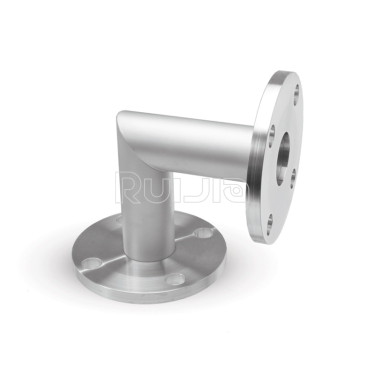
|
Temperature |
-26˚C to 200˚C |
|
Working Pressure |
Vacuum~atmosphere pressure |
|
Helium Leak Test |
1×10 -9 Pa・m³/sec or less |
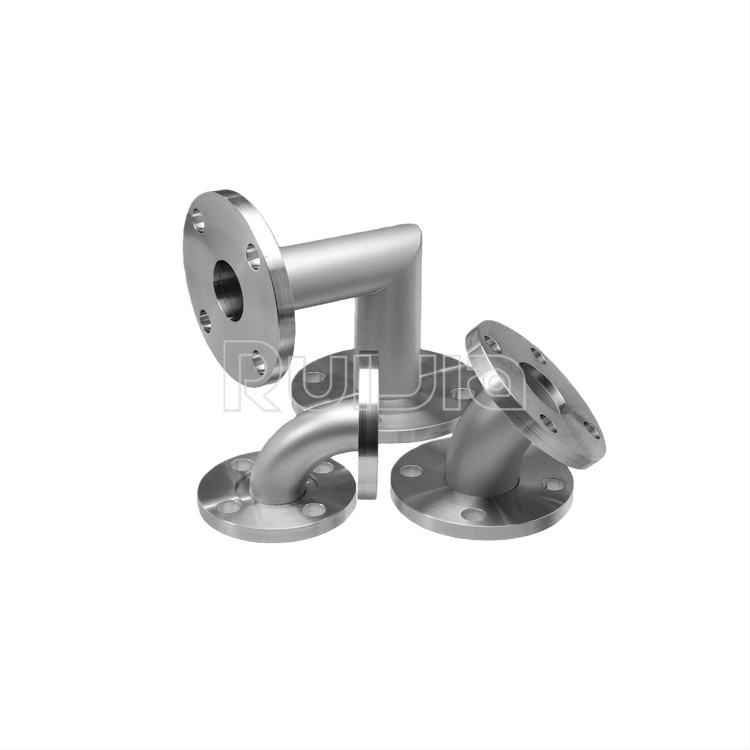
|
Temperature |
-26˚C to 200˚C |
|
Working Pressure |
Vacuum~atmosphere pressure |
|
Helium Leak Test |
1×10 -9 Pa・m³/sec or less |
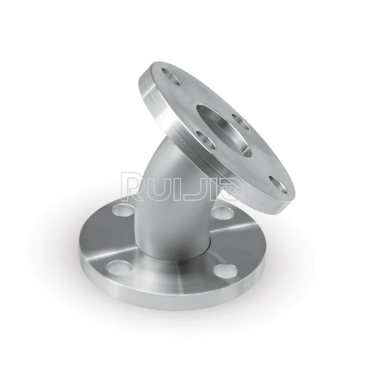
|
Temperature |
-26˚C to 200˚C |
|
Working Pressure |
Vacuum~atmosphere pressure |
|
Helium Leak Test |
1×10 -9 Pa・m³/sec or less |

Rich stock, fast delivery
Quick response within 24h
Quality assurance
Accessory replacement
GET A QUOTE