Determining adequate tightening torque for ISO-KF clamp connections, with size-based reference ranges and practical “enough” criteria.


Picture this: your coating chamber finally reaches base pressure after a 45-minute pump-down, the plasma strikes clean and bright, and then—mid-recipe—a tiny internal leak creeps in. Oxygen contamination spikes from 2 ppm to 180 ppm. The production batch is scrapped. After two days of helium spraying and RGA tracing, the culprit is identified: a shaft seal on a manually operated gate valve that nobody remembered to check during the last system rebuild.
If you have ever stood in front of a rack of vacuum hardware, wondering why seemingly similar components carry a factor-of-five price difference, you already know that selecting the right flow control device for a low-pressure environment is not about picking whatever fits the flange. It is about matching the physics of your process to the mechanics of the valve. This article walks through the six variables that matter most, shares a few diagnostic stories from the field, and offers a practical selection sequence you can use tomorrow.
Before opening a single datasheet, write down three numbers: your typical operating pressure, your maximum tolerable leak rate, and the gas species that will flow through the line. A valve that works beautifully for argon at 1×10⁻³ mbar may fail catastrophically with water vapor at the same pressure because its sealing material swells. If your process involves reactive gases—fluorine, chlorine, silane—start your search by eliminating all elastomers that are chemically incompatible; later performance discussions become irrelevant if the O-ring dissolves in the first cycle.
This is also the moment to decide between isolation, venting, and throttling functions. Many systems need a fast-acting isolation gate at the chamber inlet, while the foreline requires a soft-start angle valve to avoid turbulence during initial evacuation. Mixing these roles leads to poor conductance and premature wear.
At this point, you may want to look at a range of vacuum-compatible valve solutions designed for different pressure regimes and gas chemistries.
Once the process boundary conditions are clear, run through these six checks. They form a quick decision matrix that prevents the most common ordering errors.
1. Pressure range and sealing mechanism
From atmospheric to rough vacuum (down to ~1 mbar), elastomer-sealed ball or butterfly designs are often sufficient and cheap. Between 10⁻³ and 10⁻⁷ mbar, metal-seated gate valves or all-metal angle valves become necessary because elastomers outgas too heavily. For UHV and XHV below 10⁻⁹ mbar, only all-metal, bakeable designs with conflat flanges survive. One semiconductor fab learned this the hard way when PTFE seats in their foreline valves created a virtual leak that took three weeks to diagnose—the polymer absorbed moisture during a maintenance window and slowly released it, limiting base pressure to 5×10⁻⁶ mbar no matter how long they pumped.
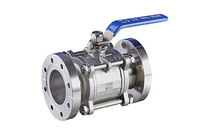
2. Conductance and port size
Valve conductance directly affects effective pumping speed. A DN 40 ISO-KF valve may have a conductance of 15–20 L/s for nitrogen at molecular flow, whereas your turbopump at that port size delivers 60 L/s. If the valve sits between pump and chamber, you are losing over 60% of your pumping capacity. I have seen a simple size increase from DN 40 to DN 63 cut chamber pump-down time by half, with no other change. Use the manufacturer’s published conductance curves—they exist for a reason.
3. Actuation and feedback requirements
Manual valves are fine for occasional isolation. For automated systems, choose between pneumatic, electromagnetic, or motorized actuators. Pneumatic actuators are fast and reliable but require compressed air infrastructure. Motorized options give you position feedback (0–100% open) and soft-start profiles, which are invaluable for processes that cannot tolerate pressure bursts. If your PLC needs to know valve status, confirm the availability of magnetic reed switches or micro-switches before ordering. Retrofitting a position sensor to a valve that has no mounting bracket is a weekend you will never get back.
4. Cycle life and maintenance access
A load-lock gate valve on a 24/7 production line may cycle 200,000 times per year. Standard bellows-sealed gates typically carry a lifetime rating of 100,000 to 500,000 cycles, but that number assumes clean operation and no particulate exposure. If your process generates dust or deposits, choose a valve with a vulcanized gate seal that can shed particles, and design the installation so the actuator can be serviced without removing the entire body from the line. One flat-panel display manufacturer cut annual valve replacement cost by 40% simply by switching to a modular design that allowed on-tool rebuilds.
5. Material compatibility
Stainless steel 304 or 316L are the default body materials. However, for HCl or HBr processes, Hastelloy internals and Kalrez® seals are almost mandatory. Aluminum bodies are light and cheap but risk galling on threaded parts and do not tolerate aggressive cleaning agents. If you operate in a cleanroom, factor in the outgassing and particulate certifications (ISO 14644-1, for instance).
6. Safety certifications
In Europe, pressure equipment may need to comply with the Pressure Equipment Directive (PED 2014/68/EU). Semiconductor tools increasingly demand SEMI S2 compliance. Ask your supplier for the declaration of conformity before the audit arrives.
Summarizing these six points in a table makes it easier to compare candidate devices side by side:
| Criterion | What to specify | Why it matters |
|---|---|---|
| Pressure range | Ultimate vacuum rating, seal type | Determines outgassing and leak tightness |
| Conductance | Valve body K-value or Cv | Directly limits pumping speed |
| Actuation | Manual, pneumatic, motorized; feedback | Defines automation fit |
| Cycle life | Lifetime cycles at rated ΔP | Drives preventive maintenance schedule |
| Wetted materials | Body, seal, bellows metallurgy | Chemical compatibility and particle control |
| Certifications | PED, SEMI, ISO | Regulatory and customer audit readiness |
When you have narrowed the field to two or three models, request a sample valve and perform an in-situ helium leak test with a calibrated mass spectrometer. Datasheet leak-tightness specs are measured under ideal laboratory conditions; your actual installation, with real misalignment and vibration, will always differ slightly.
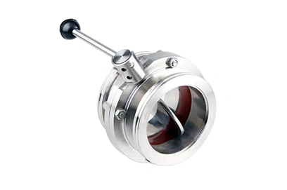
Selecting by price alone: A valve that costs $300 less at purchase but requires an unplanned eight-hour system vent and rebuild two months later is not cheaper. Calculate the cost of downtime, engineering time, and lost product. This number usually dwarfs the hardware price.
Ignoring closing time: In safety-critical applications—like a diffusion-pumped furnace that must isolate within two seconds of a power failure—valve closing speed is non-negotiable. Specify the spring-return time at the expected temperature, not at ambient.
Mismatching flange standards: ISO-KF, ISO-K, CF, ANSI, and JIS flanges are not interchangeable without adapters, which add leak points. When upgrading a legacy system, triple-check flange types before assuming “DN 40” means the same thing as the previous supplier’s “DN 40.”
Many of these pitfalls can be avoided by working with a supplier that offers a configurable range of process isolation and control devices, complete with conductance data and material certificates.
Here is a condensed, step-by-step workflow that incorporates the six checks above:
Define the worst-case process conditions — gas, pressure, temperature, cycle frequency.
Choose the sealing principle — elastomer for rough/medium vacuum, metal for high/UHV.
Calculate the minimum required conductance — aim for valve conductance ≥ 2× the effective pumping speed at the port, if possible.
Select actuator type and feedback signals — align with your control architecture.
Verify material compatibility and certifications — get certificates for wetted parts.
Request a helium leak rate test report — accepted by your quality team before installation.
Spending one hour on this sequence before generating a purchase order can save weeks of troubleshooting later. It also gives you a defensible rationale when procurement questions why you are not taking the lowest bid.
After two decades of working with vacuum systems across coating, analytical instrumentation, and heat treatment, I have developed a strong preference for valves that ship with a full set of documentation—3D CAD files, conductance charts, outgassing rate curves, and an ISO 9001 material traceability report. This level of transparency turns a commodity component into an engineered solution.
If you are at a stage where system reliability directly impacts revenue per wafer or coating batch, it might be time to look beyond generic catalogue parts. Ruijia’s portfolio of vacuum system components includes a selection of precision isolation and pressure control solutions, each backed by the testing and traceability data that process engineers routinely ask for. They serve sectors where reproducibility and low total cost of ownership are the real purchasing criteria.
One final thought: no valve will save a poorly designed vacuum system. But in a well-designed system, the right valve does more than open and close—it preserves base pressure, protects pumps, and quietly contributes to yield every single cycle.
Disclaimer: The technical information provided in this article is for educational purposes and should not replace detailed engineering analysis for specific systems. Always consult with qualified vacuum engineers and refer to the latest ISO and SEMI standards when making procurement decisions.
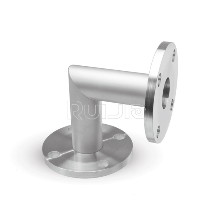
|
Temperature |
-26˚C to 200˚C |
|
Working Pressure |
Vacuum~atmosphere pressure |
|
Helium Leak Test |
1×10 -9 Pa・m³/sec or less |
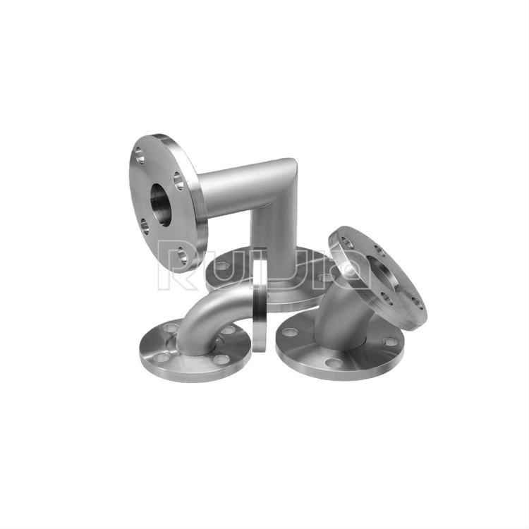
|
Temperature |
-26˚C to 200˚C |
|
Working Pressure |
Vacuum~atmosphere pressure |
|
Helium Leak Test |
1×10 -9 Pa・m³/sec or less |
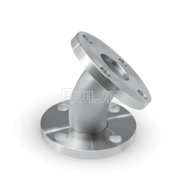
|
Temperature |
-26˚C to 200˚C |
|
Working Pressure |
Vacuum~atmosphere pressure |
|
Helium Leak Test |
1×10 -9 Pa・m³/sec or less |

Rich stock, fast delivery
Quick response within 24h
Quality assurance
Accessory replacement
GET A QUOTE