The role of bolt tightening sequence and incremental loading in achieving a reliable CF/ConFlat metal seal, using a staged 6 Nm → 20 Nm triangular reverse approach as a practical framework.


The final torque number gets the attention, but the tightening sequence decides whether a CF flange seals or leaks. Bolts must be brought up in stages, working across the flange in a triangular or star pattern, so the copper gasket compresses evenly and the flange faces stay parallel. A staged approach—for example, starting around 6 Nm and stepping toward a final value near 20 Nm in a triangular reverse pattern—is a practical way to control that load path. The exact torque values depend on flange size and bolt specification; the sequence logic applies regardless of the number on the wrench.
A CF flange does not rely on an elastomer. Two stainless steel flange faces carry a machined knife edge, and a soft copper gasket sits between them. When the bolts are tightened, the knife edges press into the copper, forcing the gasket material to flow laterally and fill the microscopic surface imperfections on both flange faces. In a typical joint, the sealing edges sink into a 1.6–2 mm thick copper gasket to a normal depth of roughly 0.36–0.40 mm per edge, generating interface pressure several times above the gasket's yield strength.
That deformation is plastic and largely irreversible. Once the copper has been compressed unevenly, a second pass cannot “average out” the error. If one side of the flange is tightened ahead of the other, the knife edge on that side bites deeper, the gasket extrudes preferentially in one direction, and the opposite side may never reach full metal-to-metal contact. The result is a joint that appears tight but leaks under helium testing or after bakeout.
The most common assumption is that any bolt brought to the correct torque contributes equally to the seal. In practice, the load path through the flange depends on the order of load application. If bolt No. 1 is taken straight to final torque while its neighbors are still finger-tight, the flange locally tilts. That tilt changes the angle at which the knife edge meets the gasket. Instead of a uniform annular indentation, you get a partial bite: deep on one side, shallow on the other. The shallow side becomes the leak path.
Ideal Vacuum's assembly guidance makes the point directly: CF connections use metal seals that are less forgiving than O-rings, and bolts must be tightened gradually and equally around the flange so the faces are brought together parallel to each other. The same guidance recommends tightening in 1/8 to 1/4 turn increments across as many as 8–10 passes, using a star or cross pattern so opposing bolts share the load. Lesker's procedure takes a similar approach—1/12 turn per bolt, moving around the flange—and emphasizes that the real target is metal-to-metal contact between the flange faces, not a torque reading alone.
CERN's finite-element and experimental work on the ConFlat joint adds a useful nuance: the tightening process has two stages. In the first stage, the flanges pivot at the gasket interface and the bolt load is essentially the gasket sealing force. Once the flange peripheries contact each other, the boundary conditions change, and further tightening straightens the flanges. A sequence that reaches peripheral contact unevenly distorts this second stage. The flange may end up “tight” without being flat.
A triangular reverse pattern is a variation of the star/cross principle adapted to flanges with 6 or 8 bolt holes. Instead of moving sequentially around the circle, you tighten a bolt, then move to the bolt roughly opposite or across the pattern, then to a third point that balances the load triangle. The goal is to keep the center of bolt load close to the gasket centerline throughout the loading history.
For a six-bolt CF flange, one practical triangular reverse sequence is:
| Pass | Bolt order (example for a 6-bolt flange) | Target |
| 1 | 1 → 4 → 2 → 5 → 3 → 6 | Hand-tight / light snug |
| 2 | 1 → 4 → 2 → 5 → 3 → 6 | ~6 Nm (first load stage) |
| 3 | 1 → 4 → 2 → 5 → 3 → 6 | ~12–13 Nm (intermediate stage) |
| 4 | 1 → 4 → 2 → 5 → 3 → 6 | Final target (e.g., ~20 Nm, per flange/bolt spec) |
| 5 | Full circle check | Confirm metal-to-metal contact; re-check torque |
The “6 Nm start to 20 Nm final” is not a universal specification. It is a staged loading framework. Published torque values for CF flanges vary with size and bolt: a small M4 fastener may have a reference maximum in the range of 1.9 Nm for a lubricated screw; DN63–DN100 CF assemblies with M8 bolts commonly fall in the 15–17 Nm range, while other CF pump connections specify 22 ± 2 Nm, with a re-check step because the gasket material continues to flow. Larger flange/bolt combinations can require higher values. The correct final number for a given joint must come from the flange or equipment manufacturer's specification, not from a generic table.
What the 6 → 20 Nm example illustrates is the principle of incremental loading: the first pass is intentionally well below final torque so that the gasket begins to compress and the flange faces align before full load is applied. Skipping the intermediate stages—or going straight to the final number on the first bolt—defeats the purpose of the sequence.
No tightening pattern can compensate for contaminated sealing surfaces or a damaged gasket. Before any bolt is turned:
If the flange uses tapped bolt holes rather than through-holes with nuts, the same sequence logic applies, but thread engagement and lubrication become more critical to repeatable torque. The available CF vacuum flange configurations include rotatable and non-rotatable bored flanges with through-hole or tapped-hole options, and the bolt-hole style affects how the wrench is applied but not the underlying loading principle.
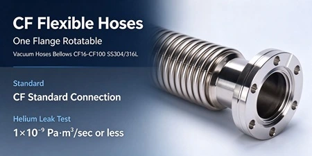
For assemblies that combine CF flanges with bellows, nipples, or adapters, the sequence should be planned across the entire joint chain, not just one interface at a time. Bringing one flange to final torque before the adjacent connection is aligned can introduce bending stress into the bellows or tube. The CF fittings and accessories range provides context for how flanges integrate with the rest of the UHV run.
A clockwise circle can work on small flanges with few bolts if the increments are very small and multiple passes are used. On larger flanges, or when the gasket is relatively stiff, a circular pattern tends to load one side progressively and can allow the flange to tilt. A cross or triangular reverse pattern distributes the load more symmetrically and is the safer default when metal-to-metal contact and bakeout leak-tightness matter.
The first bolt will locally compress the gasket before the neighboring bolts share the load. That uneven bite can prevent the opposite side of the flange from reaching full contact. The joint may hold initially and leak after thermal cycling or helium testing, because the seal is not uniformly deformed.
No universal final torque exists for all CF flanges. Torque depends on flange nominal diameter, bolt size and grade, thread lubrication, and whether the bolt is a through-bolt or a stud. Published values range from roughly 1.9 Nm for small M4 fasteners to 22 ± 2 Nm for certain CF pump connections, and higher for larger bolt sizes. Confirm the value with the flange manufacturer or equipment manual before tightening.
A re-check is advisable. The copper gasket continues to flow plastically under load, so bolt preload can drop slightly after initial tightening. Pfeiffer's CF assembly instructions explicitly include a post-tightening torque check for this reason. A feeler-gauge check for metal-to-metal contact is also useful where the geometry allows access.
CF copper gaskets are generally considered single-use components. The knife edge creates a defined indentation, and a second compression does not reliably reproduce the same sealing deformation. Reuse carries a higher risk of leak paths, particularly after bakeout or thermal cycling. If the joint must be opened, a new gasket is the safer choice.
A correctly torqued CF flange can still show a small gap between the outer flange faces; the seal is formed by the knife edges penetrating the gasket, not by the flange rims closing completely. The reliable indicators are metal-to-metal contact at the flange periphery where specified, a uniform gasket indentation, and a helium leak check. Do not keep tightening solely to close a visible gap if the specified torque and contact condition have already been reached.
The torque number is a reference point, not the objective. In a CF connection, the seal is made by uniform plastic deformation of the copper gasket under a controlled load path. A triangular reverse pattern applied in stages—starting well below the final value and stepping upward—keeps the flange faces parallel while the gasket compresses. Skipping the sequence, or treating the first bolt as a “final torque” bolt, can produce a joint that passes a casual inspection and fails under UHV conditions.
Before choosing a final torque, confirm the specification for the actual flange size, bolt size, and thread condition. The CF flange product range lists the available sizes and configurations; for a specific assembly, the bolt-hole style and gasket material should be matched to the equipment manual and the intended bakeout or cycling profile.
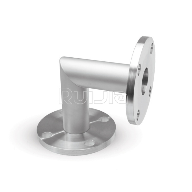
|
Temperature |
-26˚C to 200˚C |
|
Working Pressure |
Vacuum~atmosphere pressure |
|
Helium Leak Test |
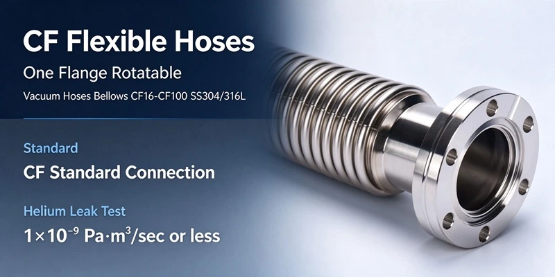
1×10 -9 Pa・m³/sec or less |
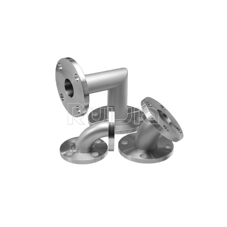
|
Temperature |
-26˚C to 200˚C |
|
Working Pressure |
Vacuum~atmosphere pressure |
|
Helium Leak Test |
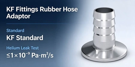
1×10 -9 Pa・m³/sec or less |
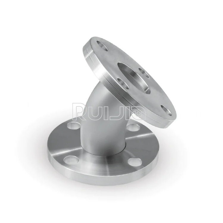
|
Temperature |
-26˚C to 200˚C |
|
Working Pressure |
Vacuum~atmosphere pressure |
|
Helium Leak Test |
1×10 -9 Pa・m³/sec or less |
Rich stock, fast delivery
Quick response within 24h
Quality assurance
Accessory replacement
GET A QUOTE