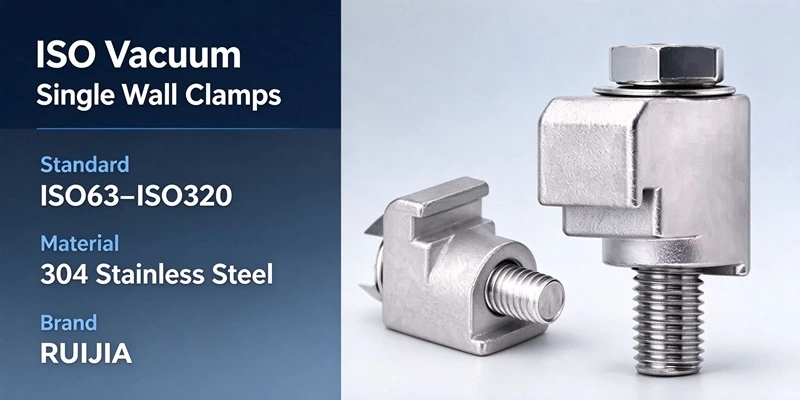
Correct tightening judgment for ISO-K claw clamp connections: torque as a reference, centering-ring contact as the functional stop, and the risks of treating torque as a sealing force.


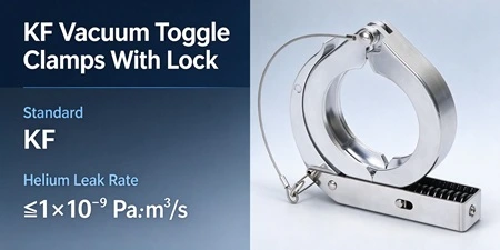
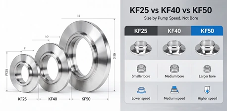
The short answer: tighten an ISO-K claw clamp to 7–10 lb-ft only as a reference range. The functional stop point is when the centering ring makes firm contact with both flange faces and a small gap remains between the metal flanges. Torque is not what creates the vacuum seal—the compressed O-ring in the centering ring does. Once that ring is seated, additional torque adds stress to the clamp, bolt, and flange without improving leak tightness.
The 7–10 lb-ft figure appears in assembly guides for ISO-K claw clamp bolts, including M10 and M12 bolt configurations used across ISO-K DN 63 through DN 250 and larger sizes. It is a practical reference for the installer: it tells you the approximate effort range in which the clamp should be brought up to its seated position, not a target that guarantees a seal.
The same guides describe the real acceptance condition: “torqued to 7–10 lb-ft or until the centering ring makes contact with the flanges,” with a small gap remaining between the flange faces. That wording matters. The torque number and the contact condition are presented together because the contact condition is the governing criterion. On a correctly assembled joint, the flange faces do not close completely. The centering ring acts as a mechanical spacer and a seal carrier at the same time.
This differs from bolted flange designs where metal-to-metal contact of the flange faces is the endpoint. In an ISO-K joint, the elastomer O-ring sits in the centering ring and is compressed against the flange sealing surfaces as the clamp draws the flanges toward the ring. The ring bottoms out before the flanges touch. Once it bottoms out, the clamp has done its job. Continuing to turn the bolt does not compress the O-ring further in a useful way—it begins to load the clamp and flange rim in a direction they were not designed to accept.
An ISO-K connection uses a centering ring that carries an elastomeric O-ring. The ring centers the seal between the two flange faces and prevents the O-ring from being pushed inward by external atmospheric pressure when the joint is under vacuum. The claw clamps hook into a ridged groove on the back side of each ISO-K flange and draw the two flange rims toward each other, compressing the O-ring against the ring and the sealing faces.
The load path is therefore: bolt → clamp claw → flange rim → centering ring → O-ring compression. The flange faces themselves are not the primary sealing interface; the O-ring against the flange sealing surface is. Because the centering ring limits how far the flanges can approach each other, the system has a built-in geometric stop. The installer’s job is to reach that stop evenly around the circumference, not to generate a target bolt load.
This is also why “leak after tightening” is often not a torque deficiency. If the centering ring is the wrong thickness, damaged, or not seated squarely, adding torque cannot correct the geometry. The clamp may feel tight while the O-ring is under-compressed on one side and over-compressed on another.
For readers confirming the seal-carrier side of the assembly, the available ISO centering ring configurations list the ring and O-ring material options used across ISO-K sizes.
Over-tightening an ISO-K clamp does not “make a better seal” past the ring-contact point. It introduces three risks:
Published assembly guidance for related flange systems likewise notes that over-tightening can cause material deformation or accelerated seal wear, and that torque should be applied at a sufficient level and checked periodically where vibration is present. For ISO-K specifically, the practical implication is that the stop point deserves more attention than the torque number.
ISO-K claw clamps should not be brought to final tightness in a single pass on one clamp. The flanges need to approach the centering ring evenly so that the O-ring compresses uniformly around the full circumference.
A practical sequence used in vacuum assembly guidance is a cross-pattern, multi-stage approach: bring the clamps up in stages (for example, a low initial stage, a middle stage, and a final stage), moving diagonally across the flange so that opposing clamps are tightened together rather than consecutively. The exact stage values depend on clamp size and bolt specification, but the principle is consistent: never let one side of the flange reach the centering ring while the opposite side is still loose.
With a multi-clamp ISO-K flange, the goal is that all clamps reach the ring-contact condition at approximately the same time. If one clamp feels “soft” while others have firmed up, stop and check whether the centering ring is seated correctly and whether the flange faces are parallel. Continuing to tighten the soft clamp to match the others can distort the assembly. For clamp body and bolt options by ISO-K size, review the available ISO clamp configurations before assembly.
The torque figure is only meaningful when the components are correct. Before tightening, confirm:
If a joint leaks after reaching the ring-contact condition at the recommended torque, the corrective action is not to increase torque. The next step is to isolate the cause: inspect the O-ring for cuts or compression set, verify centering-ring thickness and flatness, check flange parallelism, and perform a leak check at the joint. The ISO flanges and fittings category page provides an overview of the component types involved in this check.
| Condition | What it means | Action |
| Clamp bolt reaches 7–10 lb-ft and centering ring contacts both flanges with a small flange gap | Seated correctly | Stop. Proceed to leak check. |
| Clamp bolt is below the reference range but the ring is already in firm contact and the gap is uniform | Geometry has bottomed out early | Stop. Verify ring thickness and flange cleanliness; do not force torque to the number. |
| Clamp bolt is at 7–10 lb-ft but the ring is not in contact on one side | Uneven approach or misalignment | Loosen, re-center the ring, and re-tighten in a cross-pattern sequence. |
| Flange faces close completely with no visible gap | Over-tightening or wrong centering ring | Stop. Inspect ring, O-ring, and flange rim for deformation. |
No. The seal is created by the O-ring compressed between the centering ring and the flange sealing surfaces. 7–10 lb-ft is a reference range for bringing the clamp to the seated position. The functional stop is centering-ring contact with a small flange gap.
Yes, if the ring is in firm, even contact and the flange gap is uniform. The reference range assumes the components and geometry are correct; if the ring bottoms out earlier, adding torque to reach a number does not improve the seal.
The clamp and flange rim take on additional load that does not increase useful O-ring compression. Risks include clamp deformation, local rim distortion, and a false sense of security that can hide a damaged O-ring or misaligned ring.
A leak at the recommended torque usually points to O-ring damage, incorrect centering-ring size or thickness, contamination on the sealing face, or uneven clamp approach. Increasing torque is unlikely to correct these conditions and may add deformation.
No. ISO-K uses claw clamps that draw the flange rims toward a centering ring; the ring limits the travel. ISO-F is a bolted flange pattern where the fasteners directly load the flange faces. The torque values and stop criteria are specific to the connection type.
Clamp quantity depends on flange size. Common configurations range from three to four clamps on smaller ISO-K sizes up to larger counts on DN 200 and above. Confirm the required quantity for the specific flange designation before assembly.
The practical answer to “how tight should an ISO-K clamp be” is not a single torque number. 7–10 lb-ft is a useful reference for bringing the clamp up to its seated position, but the joint is correctly tightened when the centering ring is in firm, even contact with both flange faces and a small, uniform gap remains between the flanges. Past that point, additional torque adds load to the clamp and flange without improving the seal. If a joint leaks at the seated condition, the productive next step is to inspect the O-ring and centering ring, not to reach for a longer wrench. The ISO-K sealing logic is geometric before it is numerical.
To review compatible clamp, centering-ring, and flange configurations for a specific ISO-K assembly, see the ISO flanges and fittings category page.
|
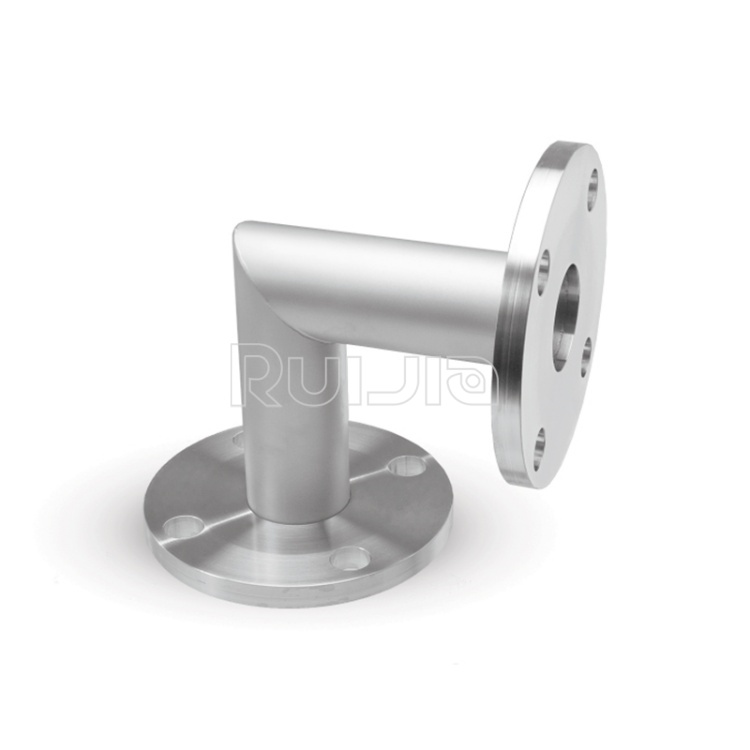
Temperature |
-26˚C to 200˚C |
|
Working Pressure |
Vacuum~atmosphere pressure |
|
Helium Leak Test |
1×10 -9 Pa・m³/sec or less |
|
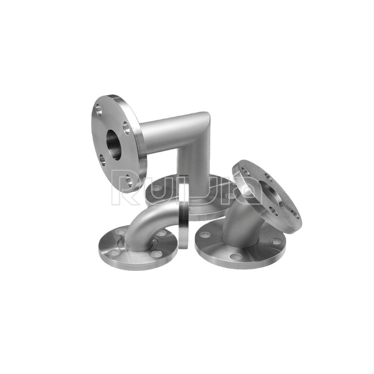
Temperature |
-26˚C to 200˚C |
|
Working Pressure |
Vacuum~atmosphere pressure |
|
Helium Leak Test |
1×10 -9 Pa・m³/sec or less |
|
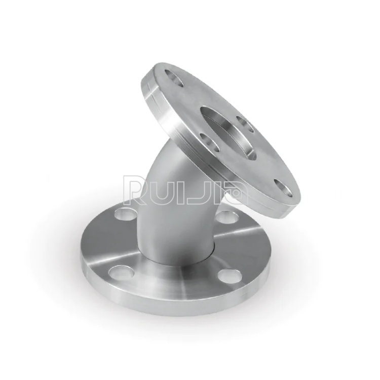
Temperature |
-26˚C to 200˚C |
|
Working Pressure |
Vacuum~atmosphere pressure |
|
Helium Leak Test |
1×10 -9 Pa・m³/sec or less |
Rich stock, fast delivery
Quick response within 24h
Quality assurance
Accessory replacement
GET A QUOTE