A mixed KF/ISO vacuum connection can leak even when the clamp feels tight. Learn how coaxiality, uneven sealing load, and adapter choice affect leak risk, and when a conical reducer is the practical fix.


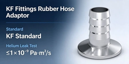
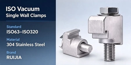
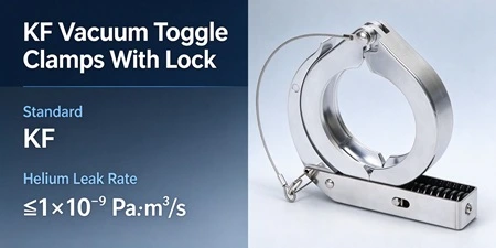
A mixed KF/ISO connection can leak even when the clamp feels fully tightened because the two flange systems locate the sealing element through different geometric references. When their axes are not coaxial, the clamp does not create uniform compression—it creates a bending moment across the sealing face. A conical reducing adapter or a dedicated transition adapter addresses this by converting the misalignment into a controlled conical fit, rather than forcing two dissimilar flange faces into an alignment they were not designed to share. The key judgment is whether the offset is small enough to be absorbed by the seal, or large enough to require a change in connection strategy.
KF and ISO are both clamped flange families, but they do not share a single dimensional datum. A standard KF joint uses two matching flange faces, a centering ring that positions the O-ring, and a clamp that closes on the angled outer surfaces of the flanges. The centering ring is the locating feature: it keeps the seal positioned between the mating faces and, in normal use, establishes the radial reference for the joint. ISO flanges, by contrast, are specified within the ISO 1609 family for non-knife-edge flanges, and their centering arrangements, outer profiles, and clamp interfaces differ from the KF quick-clamp geometry.
When a KF component is connected to an ISO component—or when a line transitions between the two families—there is no shared centering ring that simultaneously engages both flange profiles. Something else must bridge the two geometries. If that bridge is a direct clamp, the clamp is being asked to perform two functions at once: hold the joint closed and establish coaxiality between two flange axes that were never designed to be referenced to each other. A clamp is not a centering device. It applies closing force; it does not correct runout.
The sealing logic of a clamped elastomer joint depends on compression being distributed around the circumference. The O-ring or elastomer seal needs a reasonably uniform gap between the mating surfaces to compress evenly. When two flange faces are not coaxial, the gap is not uniform: one side of the seal is compressed more, the opposite side less. The clamp may feel tight because it has reached its mechanical stop or because the user has applied additional torque, but “tight” at the clamp does not mean uniform at the seal.
This is not a theoretical concern unique to vacuum hardware. Studies of clamped flange joints with noncoaxial or eccentric gasket arrangements have observed local bending of the tightened gasket, reduction of the effective seal area, and diminution of seal pressure on the less-compressed side—effects that increase the probability of leakage. The same principle applies here: the clamp closes the joint, but the geometry of the mismatched interfaces determines whether the seal sees even compression or a rocking load.
A second failure mode compounds the first. When a user responds to a suspected leak by further tightening the clamp, the additional force does not correct coaxiality—it increases the bending moment across the already uneven seal. On KF joints, over-tightening is independently recognized as a cause of flange cracking and seal damage. In a mixed KF/ISO joint, the incentive to over-tighten is stronger precisely because the joint does not “feel” seated, making the combined risk of uneven load and mechanical damage higher than in a matched-flange joint.
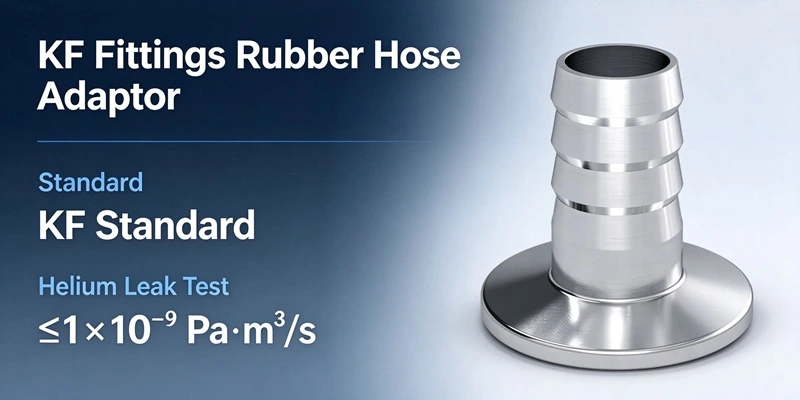
A conical reducing adapter does not eliminate the dimensional difference between KF and ISO. What it does is relocate the geometric transition away from the sealing face and into a controlled internal contour. The adapter presents a KF-compatible interface on one end and an ISO-compatible interface on the other, with a conical internal transition between them. The conical form is machined as a single controlled surface, so the runout of the transition is a defined manufacturing tolerance rather than an emergent property of two clamps pulling dissimilar flanges toward each other.
In practical terms, the adapter converts the problem from “force two flange axes into coincidence at the seal” to “join each flange to its own matching interface on the adapter, and let the adapter’s internal cone handle the diameter change.” The sealing surfaces on each side of the adapter are then loaded through their own centering features, not through a shared, misaligned clamp. Conical reducers are also designed with smooth internal transitions to limit turbulence and flow resistance at the diameter change, which matters in conductance-sensitive lines.
A tubulated adapter follows a related logic in a different form: it provides a defined transition between dissimilar flange types through a fabricated or machined body, rather than relying on the clamp alone to bridge the interfaces. The practical difference between a conical reducer and a tubulated transition is not “which one seals better” in the abstract, but which one matches the runout and length requirements of the specific line.
| Decision factor | Forcing alignment with the clamp | Conical reducing adapter or transition adapter |
|---|---|---|
| Coaxiality control | Depends on clamp force and user judgment; no defined radial datum | Established by the adapter’s machined interface and internal cone |
| Sealing load distribution | Uneven when axes are offset; one side compresses more than the other | Each flange seals against its own matching interface; load follows the adapter’s geometry |
| Runout sensitivity | High; small offsets can produce a visible gap on one side | Runout is a specified adapter tolerance, not an installation variable |
| Risk of over-tightening | Elevated, because the joint may not “feel” seated | Reduced, because each interface has a defined seating condition |
| Flow path | Abrupt diameter change at the mismatched faces | Conical or tubulated transition can be contoured to limit turbulence |
| When it is appropriate | Only when the two interfaces are dimensionally compatible and the offset is within the seal’s compression range | When the flange families differ or the axes cannot be brought into reliable coaxiality by clamping |
There is no universal threshold that separates “acceptable offset” from “requires an adapter.” The permissible offset depends on the seal material and hardness, the compression range of the specific O-ring or gasket, the flange size, and the vacuum level. A large-bore ISO joint and a small KF joint do not respond to the same absolute offset in the same way. For this reason, any statement that a particular offset is “fine” or “too much” without specifying the seal system and flange size should be treated as an approximation, not a specification.
The safer decision rule is structural rather than numerical: if the two flanges do not share a centering feature that references a common axis, and the joint relies on clamp force to hold the axes in alignment, the sealing load is inherently uncertain. A reducing adapter or transition adapter does not make the connection immune to leakage—adapter machining tolerances and installation still matter—but it changes the problem from “hold two misaligned faces together” to “seal each flange to its own controlled interface.” That is a more predictable geometry.
Not necessarily. If the two interfaces are dimensionally compatible and the seal can accommodate the actual offset without losing uniform contact, a direct clamped joint may work. The adapter becomes necessary when the flange families differ in centering geometry or when the offset produces an uneven sealing load that cannot be corrected by normal clamping.
Additional clamp force does not correct coaxiality. It increases the load on the already compressed side and the bending moment across the seal. Over-tightening is independently associated with KF flange cracking and seal damage, so increasing torque is not a reliable remedy for a misalignment-driven leak.
A conical reducing adapter uses a machined internal cone to transition between different diameters or interface standards, with the transition contained within the adapter body. A tubulated adapter provides a defined transition through a tubular or fabricated body, often for connecting dissimilar flange types. Both relocate the geometric transition away from the clamp interface; the choice depends on the required runout, length, and flow path.
Yes. An adapter is a precision component, and its concentricity and surface finish affect how each flange seats. A reducing adapter with excessive runout reintroduces the same uneven loading problem in a different location. Adapter runout should be treated as a specification to confirm, not an assumed property.
A conical transition can be designed with a smooth internal contour to limit turbulence and flow resistance, but any reduction in diameter introduces some conductance penalty relative to a straight run. The practical effect depends on the line’s operating pressure, gas load, and the ratio of the two diameters. In conductance-sensitive systems, the transition geometry should be reviewed alongside the adapter’s dimensional specifications.
Confirm both flange designations, the tube outside diameters, the required vacuum level, and the available space for the transition. Review the adapter’s interface dimensions and runout specification against the actual mating components. If the line involves additional requirements such as high-purity cleaning or material compatibility, those should be confirmed before ordering.
The most important judgment in a mixed KF/ISO connection is not how much clamp force the joint can take, but whether the two flange faces share a centering reference that keeps the seal under uniform compression. When they do not, the clamp is being used as a centering device, and the sealing load becomes a function of offset and tightening force rather than controlled geometry. A conical reducing adapter or a dedicated transition adapter does not remove the dimensional difference between KF and ISO, but it moves that difference into a machined internal transition where runout can be specified and each flange can seal against its own matching interface. Before the next mixed-line assembly, confirm the flange designations and tube dimensions, inspect the sealing-surface contact pattern rather than defaulting to more torque, and review the available adapter configurations against the actual line requirements.
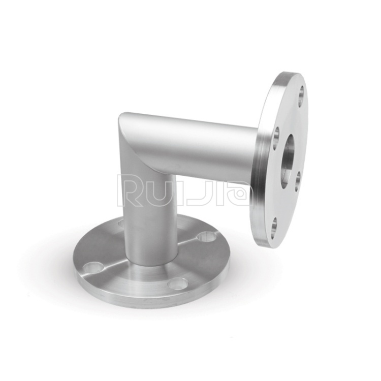
|
Temperature |
-26˚C to 200˚C |
|
Working Pressure |
Vacuum~atmosphere pressure |
|
Helium Leak Test |
1×10 -9 Pa・m³/sec or less |
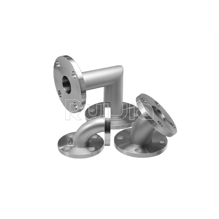
|
Temperature |
-26˚C to 200˚C |
|
Working Pressure |
Vacuum~atmosphere pressure |
|
Helium Leak Test |
1×10 -9 Pa・m³/sec or less |
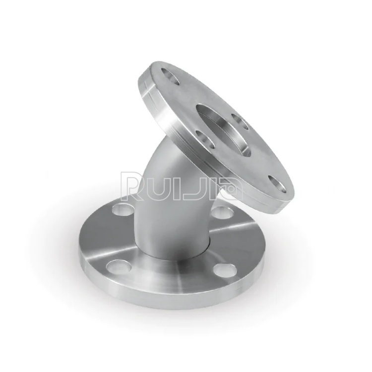
|
Temperature |
-26˚C to 200˚C |
|
Working Pressure |
Vacuum~atmosphere pressure |
|
Helium Leak Test |
1×10 -9 Pa・m³/sec or less |
Rich stock, fast delivery
Quick response within 24h
Quality assurance
Accessory replacement
GET A QUOTE