A practical engineer's guide to navigating CF flange dimensions from DN16 to DN250. Covers key parameters like flange OD, bolt circle, and number of bolts, along with material choices and common mistakes.


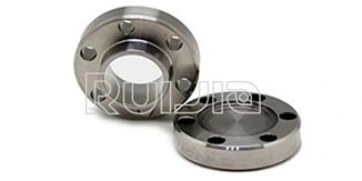
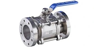
It was a routine leak check on a freshly baked UHV chamber. The residual gas analyzer kept showing a persistent water vapor peak, no matter how long we baked. After two days of troubleshooting, the culprit wasn’t a pinhole in the chamber wall – it was a mismatched CF flange on a simple right-angle valve. The bolt circle was correct, the outer diameter looked fine at a glance, but the knife-edge geometry was from a different manufacturer’s “compatible” series. A gap of less than 0.05 mm, invisible to the naked eye, kept the copper gasket from biting in evenly. That day we learned: close enough dimensions still mean open leakage in high and ultra-high vacuum work.
Such headaches often trace back to one quiet assumption – that all metal-seal flanges sharing the “CF” designation are instantly interchangeable. The reality is more nuanced, and getting the dimensions right from DN16 up to DN250 is less about memorizing tables and more about understanding which numbers actually drive sealing performance and system compatibility.
The CF series follows a nominal size logic that can surprise engineers moving over from KF or ISO systems. The “DN” number does not directly represent the inner diameter of the tubing; it’s a nominal designation. For example, a DN40 CF flange typically fits tubing with a 1.5-inch (38.1 mm) outer diameter, but the actual bore through the flange will be noticeably smaller than 40 mm. When you start plumbing a gas line or a beamline, that step change in conductance can matter.
Below is the dimension set you’ll actually reach for when specifying components or drawing up a vacuum layout. These values are based on widely accepted ISO 3669:2020 conventions, but always confirm with your supplier’s certified drawings – tolerance stack-ups in bakeable systems can shift the effective bolt circle just enough to frustrate a clean assembly.
| Nominal Size | Flange OD (mm) | Bolt Circle Dia. (mm) | Number of Bolts | Bolt Thread | Typical Bore (mm) |
| DN16 | 34.0 | 27.0 | 6 | M4 | 16.0 |
| DN25 | 54.0 | 41.0 | 6 | M5 | 25.4 |
| DN40 | 70.0 | 57.2 | 6 | M6 | 38.1 |
| DN50 | 86.0 | 72.4 | 8 | M8 | 50.8 |
| DN63 | 114.0 | 92.2 | 8 | M8 | 63.5 |
| DN100 | 152.0 | 130.3 | 16 | M8 | 101.6 |
| DN160 | 202.0 | 181.0 | 20 | M8 | 152.4 |
| DN200 | 254.0 | 231.8 | 24 | M8 | 203.2 |
| DN250 | 305.0 | 284.0 | 28 | M10 | 254.0 |
Notice how the flange OD grows substantially faster than the nominal bore – by the time you reach DN250, you’re handling a 305 mm flange to accommodate a 10-inch tube. This has real-world implications for the weight of your assembly and the spacing you need to leave between adjacent ports on a vacuum chamber. We’ve seen more than one design where ports looked generously spaced in CAD, only to find that the actual flanges couldn’t be turned during installation because of interference.
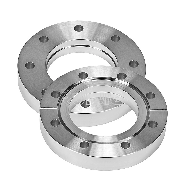
One of the most persistent errors is assuming that the bolt circle diameter alone defines alignment. While the bolt circle is critical, the knife-edge geometry, gasket retaining rim, and even the clearance hole tolerance for the bolts can create a situation where the hardware lines up but the seal doesn’t seat. In copper gasket sealed joints, the knife-edge must indent the gasket evenly around its entire circumference. If one bolt is bottoming out because of a slightly shallow threaded hole, or if the flange counterbore has an unfamiliar radius, you’ll get a slow leak that no helium sniffer will catch until the system is fully baked.
Another frequent pitfall involves material pairing. Stainless steel 304 and 316L are the default choices for most vacuum connection components, but not all 316L forgings behave the same under repeated bake-out cycles. At temperatures above 400 °C, the differential thermal expansion between a thick DN160 flange and a thin-walled welded nipple can gradually deform the knife-edge, especially if the flange was machined with excessive residual stress. A practical rule of thumb we’ve adopted from years of custom chamber builds: if your process regularly cycles above 300 °C, request flanges that have been vacuum annealed after rough machining, and verify that the material certificate shows low inclusion content.
If you are currently reviewing specific models and need detailed mechanical drawings, you can browse the available configurations and specs to cross-check against your design.
Getting the dimensions right on paper is the first step. Making sure the flange you receive matches the drawing is the second – and it’s where batch traceability starts to matter. A reputable supplier will laser-etch the heat number and size designation directly onto the flange body, not just rely on bag labels that can get mixed up in a busy assembly bay.
Beyond basic dimensions, pay attention to the following three parameters when you transition from prototyping to production builds:
Knife-edge sharpness and concentricity. The edge radius should be below 0.1 mm, and its runout relative to the bolt circle should be within 0.05 mm. This guarantees that the copper gasket is engaged progressively as you tighten in a star pattern.
Bolt thread class and depth. A minimum of 1.5× bolt diameter of thread engagement is recommended for stainless-on-stainless threads, with a class 6H fit. When assembling large flanges like DN200 or DN250, a molybdenum disulfide anti-seize compound on the bolt threads becomes essential to avoid galling.
Surface finish on the sealing side. While Ra 0.8 μm is common for the flange face, the knife-edge itself should be finer – Ra 0.4 μm or better – to prevent microporosity along the indentation line.
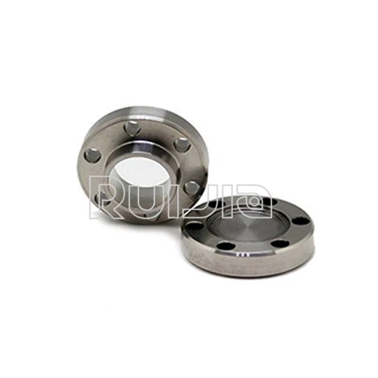
If you are working with unusual port layouts or need to transition between CF and other vacuum standards, the task shifts from picking a part number to engineering a sub-assembly. In those situations, having access to certified 3D step files and material test reports saves considerable back-and-forth. Many engineering teams find that checking the detailed flange documentation early in the design phase helps them avoid last-minute redrafts when the procurement lead times become visible.
A dimensionally perfect flange can still cause trouble if the surrounding hardware is ignored. Use only silver-plated or unplated high-purity copper gaskets – standard OFHC copper works for most applications down to 1×10⁻¹³ mbar, but for extremely low outgassing requirements, consider vacuum-fired gaskets. Never reuse a copper gasket on a baked system; the work hardening from the first compression prevents a uniform second seal.
Tighten bolts in a three-pass star sequence, gradually increasing torque to the recommended value (typically 12–18 N·m for M8 bolts on DN63–DN160 flanges, but always confirm with the manufacturer). Uneven tightening is the single most common installation error we observe during on-site service visits.
As vacuum systems grow more complex, the value of consistent, well-documented connection standards becomes hard to overstate. The difference between a system that reaches base pressure in two hours and one that struggles for eight can come down to a handful of flanges that were selected with the right combination of dimensional fidelity and material integrity.
If you are aiming to build a vacuum envelope that remains tight across hundreds of thermal cycles, you might want to explore Ruijia’s metal-seal connection solutions. The product range includes standard and custom bore sizes from DN16 through DN250, with full material traceability and dimensional inspection reports available on request.
ISO 3669:2020, Vacuum technology – Dimensions of knife-edge flanges
ISO 1609:2020, Vacuum technology – Flange dimensions
A. Roth, Vacuum Sealing Techniques, Springer, 1994
Manufacturers’ certified dimensional datasheets
Disclaimer: The dimensional table provided is for general guidance and based on commonly adopted standards. Always verify critical dimensions with the official datasheet of your component supplier before finalizing vacuum chamber designs.
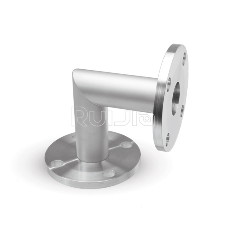
|
Temperature |
-26˚C to 200˚C |
|
Working Pressure |
Vacuum~atmosphere pressure |
|
Helium Leak Test |
1×10 -9 Pa・m³/sec or less |
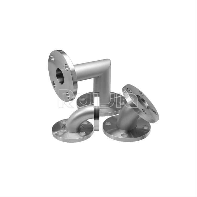
|
Temperature |
-26˚C to 200˚C |
|
Working Pressure |
Vacuum~atmosphere pressure |
|
Helium Leak Test |
1×10 -9 Pa・m³/sec or less |
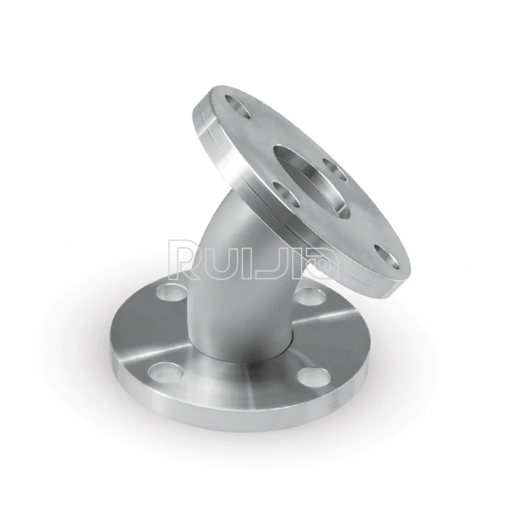
|
Temperature |
-26˚C to 200˚C |
|
Working Pressure |
Vacuum~atmosphere pressure |
|
Helium Leak Test |
1×10 -9 Pa・m³/sec or less |

Rich stock, fast delivery
Quick response within 24h
Quality assurance
Accessory replacement
GET A QUOTE