Determining adequate tightening torque for ISO-KF clamp connections, with size-based reference ranges and practical “enough” criteria.


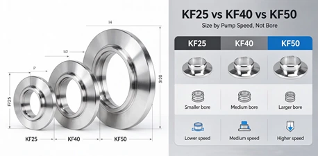
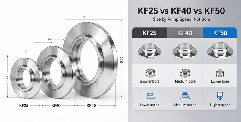
Quick answer: KF25, KF40 and KF50 share the same quick-clamp connection concept, but their internal bores differ enough to change how much of the pump’s rated speed actually reaches the chamber. The deciding variable is not the bore printed on the flange—it is the conductance of the full line relative to the pump speed at the pressure where the system must operate. When the line is short and the pump speed is modest, KF25 can be adequate. As line length, elbow count or pump speed increases, KF40 or KF50 becomes necessary to prevent the piping from throttling the pump. The reliable method is to estimate effective pumping speed, not to compare flange outer diameters.
A KF joint uses two flange faces, a centering ring, an O-ring and a clamp. The clamp and seal are the visible interface, so buyers often compare flanges by the bore they can see or by the tube outside diameter they intend to connect. That comparison is necessary for mechanical compatibility, but it is not sufficient for vacuum performance.
Gas flowing from a chamber to a pump passes through a series of restrictions: the chamber port, the line, elbows, valves and the pump inlet. Each restriction has a conductance, usually expressed in litres per second. Conductance is the inverse of resistance to gas flow. The pump has its own pumping speed at its inlet, but the chamber does not “see” that full speed. It sees an effective pumping speed governed by:
1 / Seff = 1 / Sp + 1 / C
where Seff is effective pumping speed at the chamber, Sp is the pump inlet speed, and C is the total conductance of the line between chamber and pump. This relationship is standard in vacuum engineering and is the reason a large pump can still produce slow pump-down when the line is restrictive.
A KF25 flange and a KF40 flange may look like members of the same “small quick-connect” family, but their bore difference translates into a substantial conductance difference once the line has any appreciable length. Published vacuum component guidance notes that a KF40 line has roughly 2.5 times the conductance of an equivalent KF25 run, and that connecting a KF40 pump inlet to a KF25 line can reduce effective pump speed at the chamber by 60% or more. Those figures are application-dependent, but the direction is consistent: the line, not the pump alone, decides what the chamber experiences.
Pump speed is not a single number. A rotary-vane or dry pump may have a high ultimate speed near atmosphere but lose speed as pressure falls. A turbomolecular pump’s speed depends strongly on foreline pressure. Before comparing flange sizes, confirm the pump’s actual inlet speed at the pressure range the process requires—not the catalogue peak figure.
If the pump’s usable speed in the working range is low, the line has less “excess” speed to lose, and a small flange may be sufficient. If the pump delivers high speed at the working pressure, the line becomes the limiting factor sooner.
Conductance falls as line length increases. It also falls when the gas must turn through elbows, tees, valves or adapters. A short, straight run of KF25 directly from a chamber port to a modest pump can perform acceptably. The same KF25 bore stretched over several metres, with two elbows and an angle valve, may add so much resistance that the effective speed at the chamber is a fraction of the pump’s rating.
In rough vacuum, gas flow is closer to viscous, and conductance is relatively high for a given bore. In molecular flow—typically below about 10−3 mbar for air at room temperature, depending on dimensions—conductance becomes proportional to a dimension factor and no longer benefits from pressure. A line that works at 10 mbar may become restrictive at 10−3 mbar. The KF flange itself is not the pressure limit; the elastomer seal and the system design determine the attainable vacuum level. But the size choice must be matched to the pressure range where the pump must remove gas.
The table below uses nominal bore as a general reference. Actual bore varies with tube wall thickness and manufacturer; always confirm the drawing. “Relative conductance” is a qualitative engineering guide, not a guaranteed value for every line. It reflects the approximate ratio of cross-sectional flow area and is consistent with published observations that KF40 lines offer substantially higher conductance than KF25 lines.
| KF designation | Nominal bore (approx.) | Relative conductance (qualitative, same length) | Typical role in a system |
|---|---|---|---|
| KF25 | ~25 mm | 1× (reference) | Short runs, modest pump speed, compact layouts, gauge or small port connections |
| KF40 | ~40 mm | ~2.5× that of KF25 | Pump inlet lines, medium-length runs, systems where pump speed is being throttled |
| KF50 | ~50 mm | Higher than KF40 | High-speed pumps, longer forelines, high gas load, low-pressure operation where molecular-flow resistance matters |
How to read this table: it is not a selection rule. A KF25 line with a very short run can outperform a KF40 line that is long and tortuous. The table is a starting point for estimating whether the bore is in the right range before doing the effective-speed calculation.
State the chamber volume, the target pressure and the acceptable time to reach it. These three numbers determine how much effective pumping speed the chamber actually needs. If the target is a base pressure under continuous gas load, state the gas load (outgassing plus process gas) and the required operating pressure.
Get the pump’s inlet speed at the relevant pressure range. If the pump is a dry pump or a roots-backed system, use the speed at the chamber’s working pressure, not only the ultimate pressure. If the pump curve is unavailable, request it from the pump supplier before finalising the line size.
Break the line into segments: straight tube, elbows, valves, adapters and the chamber port. Each segment has a conductance determined by its bore, length and shape. For an initial estimate, use the relative conductance ratios in the table above to compare candidate bores. For a more rigorous estimate, use the appropriate molecular or viscous-flow conductance formula for each segment and combine them in series:
1 / Ctotal = 1 / C1 + 1 / C2 + 1 / C3 + …
Valves deserve specific attention because a partially open or small-bore valve can dominate line resistance. The vacuum valve range includes KF butterfly and angle-seat options; when comparing sizes, confirm the valve’s conductance at the intended opening, not only its flange size.
Use 1/Seff = 1/Sp + 1/Ctotal. Compare Seff with the speed required to meet Step 1. If Seff is materially below the pump’s rated speed, the line is throttling the pump. Increase the bore, shorten the line, reduce the number of restrictive fittings, or accept a longer pump-down time.
Once the bore range is selected, confirm the KF size against the pump inlet, chamber port and any existing components. A KF40 pump inlet connected to a KF25 line is mechanically possible with an adapter, but the flow penalty can be significant. Review the available KF flange and fitting configurations to match the line size and seal material to the process gas and temperature. If a size transition is unavoidable, the adapter range should be reviewed with the same conductance discipline: an adapter that reduces bore adds resistance.
Mistake 1: Comparing flange outer diameters instead of bores. Two KF flanges of the same nominal family can have different tube outside diameters. The KF designation and the tube OD are related but not always identical; both dimensions need confirmation before ordering replacement or mixed-origin components.
Mistake 2: Using the pump’s peak speed as the chamber speed. The effective speed is always lower than the pump inlet speed when a line is present. Treating peak speed as available speed leads to underestimating the line’s impact.
Mistake 3: Sizing the line from the pump inlet rather than from the chamber requirement. A line that matches the pump inlet may still be too restrictive for the chamber’s gas load, especially on long runs or at low pressure.
Mistake 4: Ignoring valves and elbows until after the pipe size is fixed. A small-bore angle valve or a series of elbows can consume conductance that the straight tube calculation did not capture. Include them in the line model from the beginning.
Mistake 5: Assuming a larger flange is always “better.” A larger flange costs more, takes more space and may require a pump inlet adapter that reintroduces a restriction. The goal is not maximum bore; it is a line whose conductance does not materially reduce the effective speed below the required value.
Use this checklist when reviewing a KF line size with a supplier or during internal design review.
Yes, with an adapter, but the flow penalty should be calculated first. Reducing from KF40 to KF25 cuts the cross-sectional flow area and can lower effective pumping speed at the chamber substantially—published guidance suggests drops of 60% or more are possible in restrictive configurations. If the pump speed is high or the line is long, the adapter may turn a correctly sized pump into an undersized system at the chamber.
Often yes, if the line is genuinely short and straight and the required pressure is in the rough-vacuum range. A short KF25 run has limited conductance loss, and the pump’s speed may be modest enough that the line is not the limiting factor. The calculation in Step 4 confirms whether this is true for the specific pump curve and line length.
Both matter, but they interact. A long KF40 line can have lower conductance than a short KF25 line; a short KF25 line can outperform a long, elbow-heavy KF40 line. The reliable comparison is the calculated effective speed, not a rule based on one variable.
Consider KF50 when the pump’s usable speed at the working pressure is high, the line is long, the gas load is significant, or the system must operate at low pressure where molecular-flow conductance is limiting. KF50 also becomes relevant when the pump inlet is KF50 and reducing to KF40 would introduce a measurable restriction. The decision should come from the effective-speed calculation, not from a fixed length threshold.
No. A valve adds resistance; it does not compensate for a small line. A KF25 valve on a KF25 line further reduces conductance. When selecting the line size, account for the valve’s conductance at the intended opening. If the valve is restrictive, a larger line or a different valve type may be needed.
The system may reach a lower effective pumping speed than expected, extending pump-down time and potentially failing to reach the target pressure under gas load. The pump itself may appear to be operating normally, which makes the problem harder to diagnose. The risk is highest on long lines, lines with multiple elbows or valves, and systems operating at low pressure.
The decision among KF25, KF40 and KF50 is not a question of which flange “looks big enough.” It is a question of how much of the pump’s speed survives the trip through the line. Calculate the line conductance, calculate effective pumping speed, and compare it with the speed the chamber actually needs. If the line is short, straight and matched to a modest pump, KF25 can be the rational choice. If the line is long, the pump speed is high, or the system must hold a low pressure under gas load, KF40 or KF50 may be necessary to avoid throttling the pump.
Before finalising the size, review the actual bore and tube dimensions, not only the KF label, and include valves and adapters in the conductance estimate. The KF flange and fitting range provides the dimensional reference for the final configuration check. If the project involves a line that transitions between sizes or connects to a non-KF port, discuss the conductance impact with the component supplier before release.
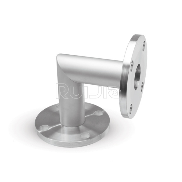
|
Temperature |
-26˚C to 200˚C |
|
Working Pressure |
Vacuum~atmosphere pressure |
|
Helium Leak Test |
1×10 -9 Pa・m³/sec or less |
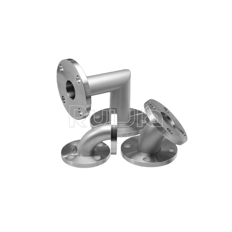
|
Temperature |
-26˚C to 200˚C |
|
Working Pressure |
Vacuum~atmosphere pressure |
|
Helium Leak Test |
1×10 -9 Pa・m³/sec or less |
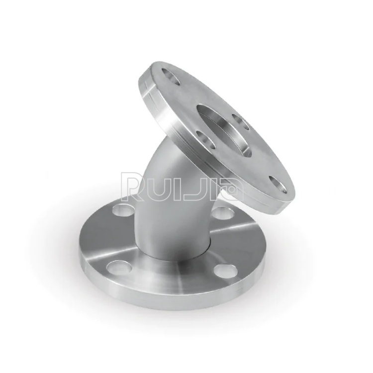
|
Temperature |
-26˚C to 200˚C |
|
Working Pressure |
Vacuum~atmosphere pressure |
|
Helium Leak Test |
1×10 -9 Pa・m³/sec or less |
Rich stock, fast delivery
Quick response within 24h
Quality assurance
Accessory replacement
GET A QUOTE