Discover how the KF flange system creates reliable vacuum seals through its O-ring and clamp design. Learn installation tips, common mistakes, and how to select quality components for leak-free vacuum systems.

You’ve just spent an hour chasing a leak in your high-vacuum chamber. The pressure won’t hold. You check the pump, the gauge, the chamber walls. Then you find it: a subtle, invisible leak right at a flanged joint. It’s the same joint you assembled last week. You tightened everything, you used a new O-ring—why is it still failing?
If this scenario feels familiar, you’re not alone. Reliable sealing is one of those things that separates a productive vacuum system from a constant debugging nightmare. And for small-bore vacuum lines—think backing lines, foreline traps, and analytical instruments—the most common go-to connection standard is a clever, quick-release design that has been around for decades but is often misunderstood.
Before we dive into how the seal actually works, a quick note: If you’re currently sizing up components for a new or rebuilt system, getting the flange geometry and material right from the start saves endless rework. A carefully selected set of vacuum-tight quick-connect components can eliminate many common installation errors.
Many people assume this type of vacuum fitting seals like a compressed gasket between two flat faces—tighten the clamp, squash the O-ring, done. That’s only part of the picture, and misunderstanding it leads to most of the leaks I’ve seen in the field.
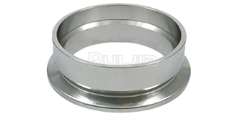
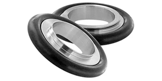
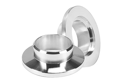
The actual sealing mechanism relies on a specific sequence of interactions between three precision components: the two flange faces, the centering ring with an integrated O-ring, and the clamp that holds them all together. The flange faces are not flat; they have a subtle tapered lip on the inner edge. The centering ring—often made of stainless steel or aluminum—carries an elastomer O-ring (Viton, Buna-N, or silicone, depending on the application). When the clamp is tightened, its angled inner surfaces engage the outer rim of both flanges, pulling them axially toward each other. The O-ring then contacts the tapered surfaces and deforms elastically, creating a wedge seal. This means the seal is face-sealing and radial-sealing simultaneously, with very little compressive force needed on the O-ring itself.
This is what makes the system so forgiving yet so reliable when assembled correctly: the centering ring aligns the two flanges perfectly, preventing offset that could distort the O-ring, and the clamped preload is distributed evenly around the circumference. The O-ring isn’t crushed; it’s gently pressed into a controlled deformation zone defined by the flange geometry.
1. Flange preparation
Cleanliness is everything. Even a single hair across the sealing surface can create a virtual leak path. Use isopropyl alcohol and a lint-free wipe on both flange surfaces and the centering ring. Inspect for scratches on the tapered area—anything that catches a fingernail can compromise the seal.
2. O-ring selection and placement
The O-ring sits in the groove of the centering ring, not loosely on the flange face. Make sure the elastomer matches your process. Viton works for most high-vacuum applications up to around 200°C; Buna-N is fine for rough vacuum and costs less. Silicone can handle lower outgassing but is mechanically weak. Place the centering ring between the two flanges. It will self-locate because of its outer diameter, but check that it is sitting flush.
3. Clamp engagement
This is where most mistakes happen. The clamp—sometimes called a speed clamp—must engage the outer rims of both flanges evenly. Tighten the wing nut until you feel firm resistance, and then give it no more than one-eighth to one-quarter turn beyond that. Unlike a copper gasket seal where you torque to a specification, this seal relies on a spring-like clamping force. Overtightening bows the flanges inward or outward, distorting the taper and causing a leak that wasn’t there before assembly.
To see this process demonstrated and to browse precision-made hardware that eliminates tolerance mismatches, you can review specific assembly guidelines and product specifications.
4. Testing
Once assembled, a helium leak test is the gold standard. Spray helium around the joint while the system is connected to a helium-sensitive leak detector. If you see a spike, loosen the clamp slightly and re-tighten—sometimes the O-ring needs to resettle.
Misconception 1: “Tighter is always better.”
As explained, overtightening destroys the taper geometry. If you see witness marks on the flange rim or the O-ring squeezing out of the gap, you’ve gone too far. A correctly seated O-ring is almost completely hidden inside the metal parts.
Misconception 2: “Any centering ring fits any flange.”
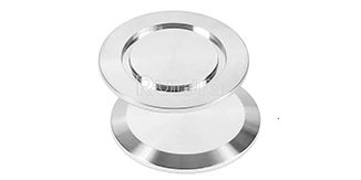
There are variations. Standard centering rings have a hole or a screen for particle filtration; some include a captive O-ring, while others use a loose O-ring. The thickness and outer diameter must match the nominal size (DN16, DN25, DN40, etc.). Mixing a DN40 clamp with a DN50 flange will never seal. Always verify that all three components—flanges, centering ring, clamp—share the same nominal diameter standard, as defined in ISO 2861.
Misconception 3: “I can reuse an O-ring indefinitely.”
Over time, elastomers take a compression set, losing their ability to spring back. If you open a joint for maintenance and the O-ring feels flat on the sealing side or shows cracks, replace it. Viton rings in frequently cycled systems should be swapped every 10–20 cycles, depending on bakeout temperature.
If you’ve followed the steps and still have a leak, here’s a practical checklist I’ve used on service calls:
Swap the O-ring material. If you’re using Viton and seeing a slow virtual leak due to moisture, silicone might give you cleaner pump-down characteristics.
Check flange alignment. Use a straight edge across the tube axis. Angular misalignment greater than 1–2° prevents the centering ring from seating evenly.
Measure the flange taper with a dial indicator. Over years, repeated overtightening can permanently yield the stainless steel, making the angle shallower. No O-ring will seal reliably against a deformed lip.
Evaluate vibration. Pumps and turbo controllers vibrate. If a clamp is loose enough to rotate by hand after a few hours, use a vibration-resistant locking wing nut or add a light thread-locking compound (avoid contaminating the clean side).
For those who’d rather not debug flange geometry one joint at a time, it often pays to start with consistent, dimensionally stable parts. Many labs and OEMs turn to a curated inventory of reliable vacuum connection hardware to minimize assembly variance across multiple ports.
Once the basic sealing mechanism is understood and mastered, a few advanced points can extend the life of your system and improve ultimate pressure:
Material pairings matter. Stainless steel flanges with aluminum centering rings can cause mild galvanic corrosion if moisture is present. In humid environments, stick to stainless steel centering rings or use a thin film of vacuum-compatible grease (sparingly—excess grease becomes a contaminant).
Bakeout considerations. If you bake the system to achieve UHV pressures in the KF range (typically down to 10⁻⁸ mbar), remember that the clamp expands differently than the flange. After bakeout, let the joint cool, then recheck the wing nut tension. You’ll often find it slightly loose.
Consider semi-permanent upgrades. For ports that are rarely opened, some engineers use a static KF sealing ring with a metal seal instead of an elastomer. This eliminates permeation and long-term compression set but requires higher clamping force.
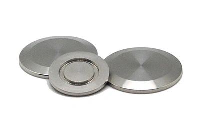
In all these scenarios, having access to technical support and a broad range of compatible parts—blank flanges, clamps of different wing nut styles, centering rings with built-in filters—turns a standard connection into a truly optimised vacuum joint. Ruijia offers a full selection of these precision-built components, with material certifications and dimensional inspection reports that help you avoid the variability that leads to mystery leaks.
A KF flange seal is an elegant piece of mechanical design that works beautifully when its three parts are matched, clean, and gently tightened. The moment we treat it like a brute-force compression fitting, it becomes a source of frustration. Next time you face a puzzling vacuum leak, don’t start by cranking the clamp harder. Instead, break the joint, inspect the taper, replace the O-ring, and reassemble with just enough clamp force to feel the wing nut seat. You’ll likely find the problem—and the seal—will hold.
Disclaimer: This article provides general guidance based on field experience and publicly available standards such as ISO 2861. It does not replace manufacturer-specific instructions or professional vacuum system design. Always verify component compatibility with your specific process conditions.
|
Temperature |
-26˚C to 200˚C |
|
Working Pressure |
Vacuum~atmosphere pressure |
|
Helium Leak Test |
1×10 -9 Pa・m³/sec or less |
|
Temperature |
-26˚C to 200˚C |
|
Working Pressure |
Vacuum~atmosphere pressure |
|
Helium Leak Test |
1×10 -9 Pa・m³/sec or less |
|
Temperature |
-26˚C to 200˚C |
|
Working Pressure |
Vacuum~atmosphere pressure |
|
Helium Leak Test |
1×10 -9 Pa・m³/sec or less |

Rich stock, fast delivery
Quick response within 24h
Quality assurance
Accessory replacement
GET A QUOTE