It is 2 a.m. at a thin‑film coating facility, and the batch that should have reached base pressure hours ago is stuck at 5×10⁻² mbar. A technician traces the source—a single vacuum joint that has been tightened repeatedly, yet still leaks. Across mid‑size process plants, joint‑related faults account for over 40% of unplanned vacuum system downtime, according to maintenance logs collected by a third‑party field‑service team. When a process chamber cannot pull down, the cost is measured in lost throughput, scrapped product, and diagnostic hours that could have been avoided by understanding the sealing principle at the heart of most small‑bore vacuum lines.
The Real Reason Your Vacuum Joints Leak
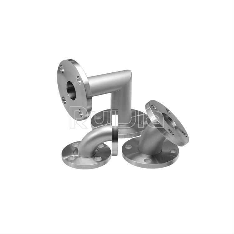
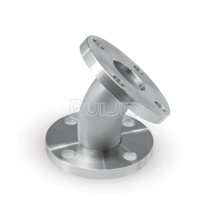
Many maintainers approach vacuum connections the same way they would a pressurized water flange: if it leaks, bear down on the bolts. This instinct is precisely what sabotages a quick‑release vacuum seal. In these joints, the sealing force does not come from crushing a flat gasket. Instead, a raised, sharp‑edged ridge on each flange face is pressed into an elastomer O‑ring that sits inside a centering ring. The O‑ring deforms elastically, creating a leak‑tight barrier without the need for high clamping torque.
Over‑tightening collapses the flange gap beyond its design geometry, which can push the O‑ring out of its groove and extrude it into the vacuum side. Once the elastomer is damaged, no amount of extra torque restores vacuum integrity. Data from a leak‑testing laboratory indicated that roughly 35% of returned small‑bore vacuum hardware showed classic O‑ring extrusion marks caused by over‑zealous tightening. Even a near‑invisible scratch on the sealing face—0.02 mm deep—can sustain a leak rate of 1×10⁻⁵ mbar·L/s, sufficient to prevent a turbopump from reaching ultimate pressure.
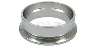
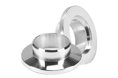
The Centering Ring: Small Part, Big Consequences
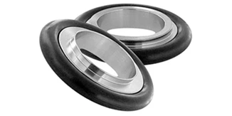
The centering ring is easy to overlook, but it performs three critical jobs: it holds the O‑ring in symmetrical alignment, prevents the O‑ring from creeping inward under vacuum, and keeps the two flange halves axially aligned. Standardized under ISO 2861, these rings are offered with elastomers that span general‑purpose nitrile (NBR), fluoroelastomer (FKM) for chemical resistance and high‑temperature cycling, and perfluoroelastomer (FFKM) for aggressive semiconductor environments.
Mixing materials with the process chemistry is a frequent, preventable failure mode. In one documented case at a pharmaceutical freeze‑dryer facility, repeated seal failures disappeared when maintenance swapped NBR centering rings for FKM after discovering that low‑concentration hydrogen peroxide vapor was attacking the rubber. The flange geometry remained unchanged; only the O‑ring material changed.
Equally important is the machining precision of the centering ring groove. A proper ISO‑compliant ring provides enough radial clearance for the knife edge to compress the elastomer by 20–30% without bottoming out. Too much clearance and the O‑ring squirms; too little and the metal ridge hits the groove floor, limiting compression and creating a leak path. When specifying these components, it is wise to look beyond the O‑ring alone and evaluate the entire centering ring design—especially for applications involving bake‑outs or corrosive cleaning agents. Explore material-specific configurations to match process conditions.
How to Choose the Right Vacuum Connection for Your System
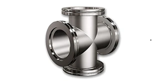
Before ordering components, three variables deserve attention: target vacuum level, process chemistry, and the mechanical environment. Quick‑release, small‑bore joints are rated from rough vacuum into the 10⁻⁸ mbar range with correct assembly, but they are not universal. Below 10⁻⁸ mbar, metal‑to‑metal seals become necessary because elastomer permeation limits pump‑down. For the vast majority of industrial and research applications—glove boxes, thermal chambers, analytical instruments, thin‑film coaters—the convenience and speed of these joints outweigh their marginally higher base‑pressure floor.
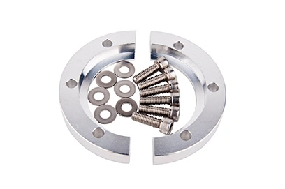
Clamp selection is the second decision point. A simple wing‑nut clamp serves glassware lines that require frequent disassembly, but systems subject to vibration or thermal cycling often benefit from toggle clamps that apply consistent, even force. Thermoplastic clamps provide electrical insulation but can creep under constant load and gradually reduce seal force. Stainless steel clamps with precision hinge pins maintain clamping force over years of cycling, a difference that shows up in baseline leak‑rate trends.
An often‑missed risk is dimensional tolerance stacking. Although nominal sizes such as 16 mm, 25 mm, or 40 mm inner diameter are standard, the outer diameter of the flange face, the pilot bore depth, and the clamp‑shoulder clearance can differ across suppliers within permissible tolerances. A system built from mixed sources may develop intermittent leaks that are frustratingly difficult to localize. Using a compatible vacuum hardware family reduces this alignment risk.
Installation Techniques That Extend Seal Life
A disciplined assembly routine prevents most chronic leaks.
-
Clean the Knife‑Edge Faces. Wipe each flange ridge with a lint‑free cloth moistened with isopropyl alcohol. Even a particle a few microns across can embed into the O‑ring and create a permanent leak path.
-
Inspect the Centering Ring. Run a gloved fingertip over the O‑ring to feel for cuts, flat spots, or swelling. A damaged O‑ring may momentarily seal but will release absorbed gas over hours, causing a slow pressure rise. Replace the entire centering ring if the metal groove shows corrosion or deformation.
-
Align Before Clamping. Bring the flanges together with only axial force. The centering ring must seat evenly before clamp pressure is applied. A misalignment of half a millimeter can prevent the knife edges from finding their track in the elastomer.
-
Stop Tightening at First Resistance. Run the wing nut until definite resistance is felt as the knife edges engage the O‑ring. If the manufacturer specifies a quarter‑turn beyond contact, apply only that. If the joint leaks at this stage, do not crank harder—disassemble, inspect, and correct the source.
-
Verify with a Leak Check. A portable helium leak detector or a simple pressure‑rise test after roughing confirms the seal. Track the baseline leak rate over time; a creeping increase signals that O‑rings or flange surfaces need attention before a critical failure occurs.
In high‑duty‑cycle environments, studies published by vacuum component manufacturers show that controlled assembly procedures can double O‑ring lifespan compared with unguided, “feel‑based” tightening.
When to Move from Reactive Repairs to a Reliability Strategy
Swapping O‑rings after a leak is discovered remains the most expensive way to manage vacuum integrity. Progressive maintenance teams are adopting condition‑based approaches: logging joint leak rates during scheduled pump‑down tests and using trend data to predict end‑of‑life for centering rings. The data frequently reveal that a handful of frequently opened ports account for over 70% of all interventions.
For organizations that depend on vacuum for their core processes, the true cost of a leak includes not just the part, but the labour, lost throughput, and contamination risk. Replacing a worn component with an identically dimensioned but metallurgically inferior copy may save a few dollars at the order desk but multiplies long‑term cost through reduced mean time between failures. A supplier that provides full material traceability and compliance certificates becomes a business advantage, not merely a purchasing checkbox.
A Smarter Way to Keep Your Vacuum Tight
Reliable sealing is never the achievement of a single part. It emerges from the interplay of flange geometry, centering ring accuracy, clamp force, and the discipline of the hands that assemble it. Each detail—groove tolerances, elastomer selection, surface cleanliness—shifts leak rate by orders of magnitude.
Ruijia has built its vacuum connection product family around these realities. By integrating precision machining with documented, batch‑level quality control, the line reduces the variance that leads to early seal degradation. For teams that want to move beyond wrestling with leaks and toward stable, repeatable vacuum performance, exploring a complete, traceable offering is the natural next step. Discover how a purpose‑built design lifts reliability across the entire system.