Every vacuum technician has faced that moment of hesitation: you’re assembling a new gas line or rebuilding a process chamber, and you’re staring at two seemingly similar quick-release fittings. One uses a simple wing-nut clamp, the other requires multiple bolts or a heavy claw clamp. They both look like they could work—until a tiny leak tells you otherwise.
If you’ve ever scratched your head over whether to use a KF-style or an LF-style coupling, you’re not alone. The confusion usually stems from their overlapping DN ranges and the fact that both belong to a globally recognized family of standardized vacuum connections. When specifying these components, engineers often narrow down their choices to two workhorse types within the broader category of ISO flanges: the lightweight, tool-free KF (Klein Flange) and the robust, metal-sealed LF (ISO-F) design. Making the right call starts not with the flange size, but with understanding what happens at the seal interface under your specific operating conditions.
If you are currently mapping out your vacuum infrastructure and want to explore a complete range of ready-to-integrate hardware, you can browse vacuum connection solutions that cover both clamping and bolted designs.
The clamping philosophy: elastomer vs. trapped metal
The fundamental divide between these two styles is how they compress the sealing element.
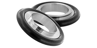
ISO-K (often called KF for Klein Flange) relies on a circumferential clamp that squeezes two identical, flat-faced flanges against a centered O-ring. The sealing force is applied by tightening a single wing nut on the clamp. This simplicity is its greatest strength—no tools needed, no bolts to drop, and quick disconnect in seconds. Sizes typically range from KF10 to KF50, making KF the default choice for roughing lines, backing pumps, and small-diameter foreline connections. However, the O-ring imposes a practical limit: elastomer outgassing and permeability make ISO-K less ideal for ultra-high vacuum (UHV) unless baked carefully and with specific material choices.
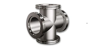
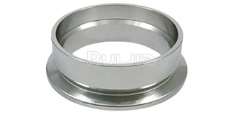
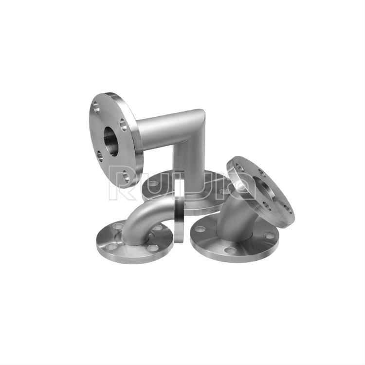
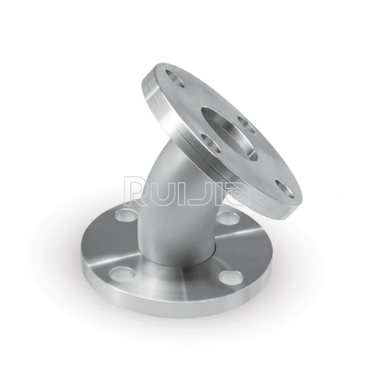
ISO-F (often referred to as LF or bolted flange) works on a different principle. Here the flange faces are not identical: one side carries a circular groove that traps a metal O-ring, typically made of copper, aluminum, or silver-plated material. The mating flange has a raised knife-edge or flat sealing surface that bites into the metal gasket as you progressively tighten a series of bolts or use a two-piece claw clamp. This metal-to-metal seal can withstand bakeout temperatures well beyond what an elastomer can survive, which is why ISO-F is the backbone of high vacuum and UHV systems from DN63 up to DN630 and beyond.
This contrast becomes clearer when laid out side by side.
| Feature |
ISO-K (KF) |
ISO-F (LF) |
| Seal type |
Elastomer O-ring (FKM, nitrile) |
Metal ring (Cu, Al, Ag-plated) |
| Clamping method |
Single wing-nut clamp or quick clamp |
Multiple bolts or claw clamp |
| Typical DN sizes |
DN10–DN50 |
DN63–DN630 |
| Pressure range |
Rough vacuum to high vacuum (10⁻⁸ mbar) |
High vacuum to UHV (10⁻¹¹ mbar) |
| Bakeout capability |
Limited (O-ring rated ~150°C) |
Up to 250°C+ with appropriate gasket |
| Assembly speed |
Very fast, tool-free |
Slower, requires torque control |
| Seal surface sensitivity |
Tolerant of minor scratches |
Sensitive; knife-edge defects cause leaks |
| Common applications |
Pump connections, gas transfer lines, bypass circuits |
Process chambers, beam lines, semiconductor tools |
Where users get burned: three real-world pain points
Even seasoned technicians learn expensive lessons from these interfaces. One recurring issue is over-tightening ISO-K clamps. Because the wing nut is easy to crank down, users often deform the O-ring, causing it to extrude into the vacuum side and create a slow, stubborn leak that defies helium testing. The fix is disciplined torque and periodic O-ring replacement—a five-cent ring can waste hours of troubleshooting.
A second trap is mixing rotational and fixed ISO-F flange halves incorrectly. ISO-F comes in two sub-variants: fixed (unrotatable) and rotatable (with a loose ring that allows bolt-hole alignment). If you bolt a fixed flange to another fixed flange without a rotatable counterpart, you may find the bolt holes misaligned and unusable. This is a common snag when ordering replacement parts in a hurry.
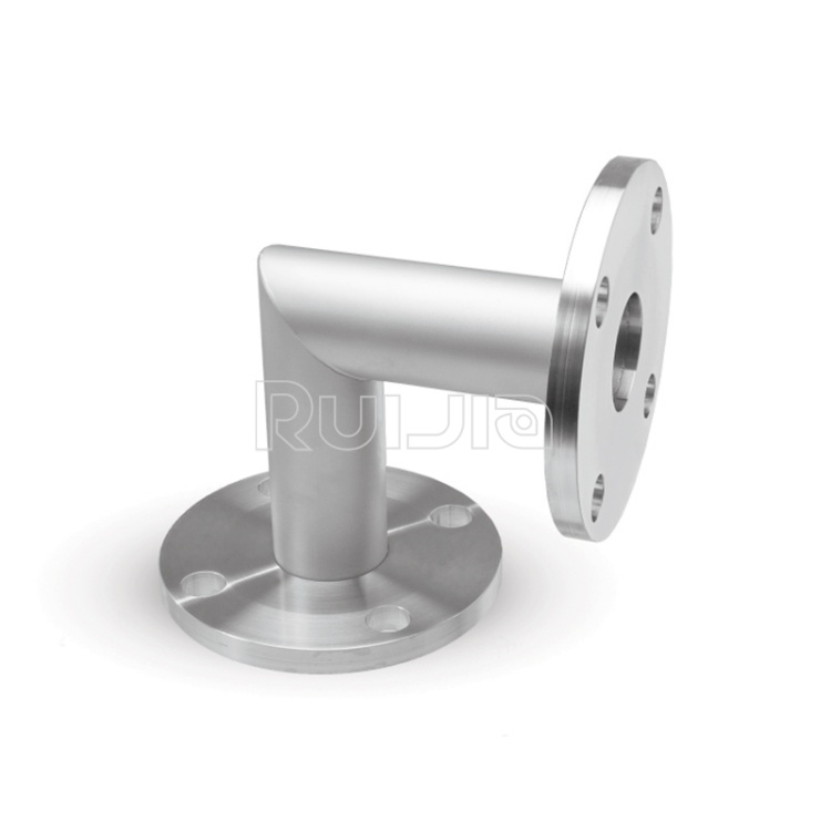
A third blind spot is size transition. Many systems evolve from rough vacuum to high vacuum sections, and the natural transition point is around DN63. At this crossover, you may need a KF-to-ISO-F adapter. Understanding the seal interface on both sides—and ensuring the adapter’s centering ring and gasket material match the vacuum regime—prevents a mismatch that can compromise the entire system’s base pressure.
For those handling larger chamber diameters or frequently reconfiguring vacuum lines, a closer look at available fitting types and specifications can prevent long-term downtime from incompatible connections.
Making the right choice: a quick mental checklist
Rather than memorizing every datasheet, you can filter your decision through three questions:
-
What is my target base pressure? If you’re staying above 10⁻⁷ mbar, ISO-K with a quality FKM O-ring usually suffices. Approaching or crossing into the 10⁻⁹ mbar region strongly favors ISO-F metal seals.
-
Will the joint be baked? Any thermal cycling above 150°C pushes you toward metal seals. Even a single bakeout cycle can cook a standard KF O-ring into a hardened, leaky lump.
-
How often will I break this connection? Daily tool swaps on a foreline call for the speed of a KF clamp. A chamber flange that gets opened twice a year for preventive maintenance can justify the longer assembly time of ISO-F.
There is also a practical consideration that many textbooks skip: inventory. Shops that standardize on one type across a narrow DN range spend less time chasing forgotten centering rings or the correct bolt length. When you do need to bridge the two worlds, a well-designed adapter that respects both the elastomer and metal sealing principles is worth its weight in uninterrupted process time.
Moving beyond the flange to the whole system
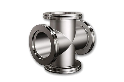
Choosing between ISO-K and ISO-F isn’t just about the flange itself—it’s about how the connection integrates with your tubing, valves, and chamber ports. A perfectly sealed flange means little if the connected tube weld introduces a virtual leak or if the valve’s conductance chokes your pumping speed. That’s why leading vacuum hardware suppliers often provide not just standalone fittings but complete subassemblies tested for leak tightness and dimensional tolerance.
If you want a reliable foundation for your vacuum infrastructure, Ruijia offers a curated lineup that covers both quick-clamp and bolted configurations, with engineering support to help you navigate the transition from rough to high vacuum regimes. Take a look at the full product lineup of KF and LF components to see what matches your next build or retrofit.
Whether you are constructing a new system from scratch or maintaining existing ISO flanges in a production environment, the difference between a temperamental leak and a stable baseline often comes down to matching the sealing principle to the application’s thermal and mechanical reality. Understanding the two primary interface types is the first step toward designing vacuum systems that just work—quietly, reliably, and for years.
References: ISO 1609 (vacuum technology – flange dimensions), ISO 2861 (KF flanges). This article is for informational purposes only and does not replace manufacturer specifications for critical applications. Always verify material compatibility and torque values against your specific operating conditions.