Learn how KF bellows compression works, what affects compression ratio, and how to select the right compressible vacuum bellows for your system. Practical engineering guide.

A vacuum line that looks neat on paper often becomes a headache during assembly. You have a pump on one side, a chamber on the other, and a pressure gauge that needs to live somewhere in between. Suddenly you’re staring at a pile of connectors, wondering whether a simple elbow will do, whether you should branch off with a tee, or if a cross will save you from threading three separate connections into an already cramped space.
The difference between these three components isn’t just about geometry. It dictates how gases flow, where stress concentrates, and how easy your system will be to service six months from now. If you’re designing or maintaining a vacuum setup — whether in a coating lab, a freeze dryer, or a mass spectrometer — a clear understanding of elbows, tees, and crosses helps you avoid chronic leaks and unplanned rebuilds. Before diving into each type, it helps to have a reference point for the wider family of quick-release vacuum connection components that these pieces belong to.
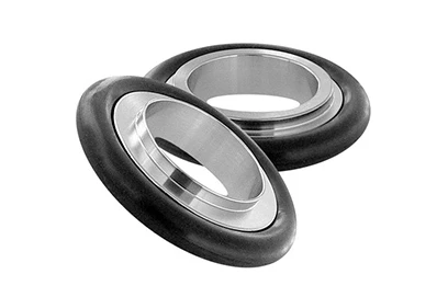
Without going too deep into the history, KF (Klein Flansch, or “small flange”) connections follow the ISO 2861 standard. They use a centering ring with an O-ring, pressed between two flanges by a clamp, to create a quick, tool-free seal that holds reliably from atmospheric pressure down to about 10⁻⁸ mbar. The system’s modularity is exactly why elbows, tees, and crosses exist as off-the-shelf building blocks: you can reconfigure a line without welding or machining.
But that flexibility comes with a choice load. Each geometry bends, splits, or distributes the flow path differently. A wrong call shows up as a higher base pressure, a slower pump-down, or a leak that moves slightly every time you bump the rack. Let’s break them down one by one.
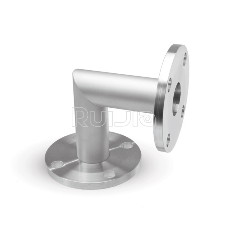
The elbow is the first component most people reach for when a straight line won’t fit. Available mostly as 90° and sometimes 45° pieces, its job is simple: change the direction of the vacuum line while preserving the same nominal diameter.
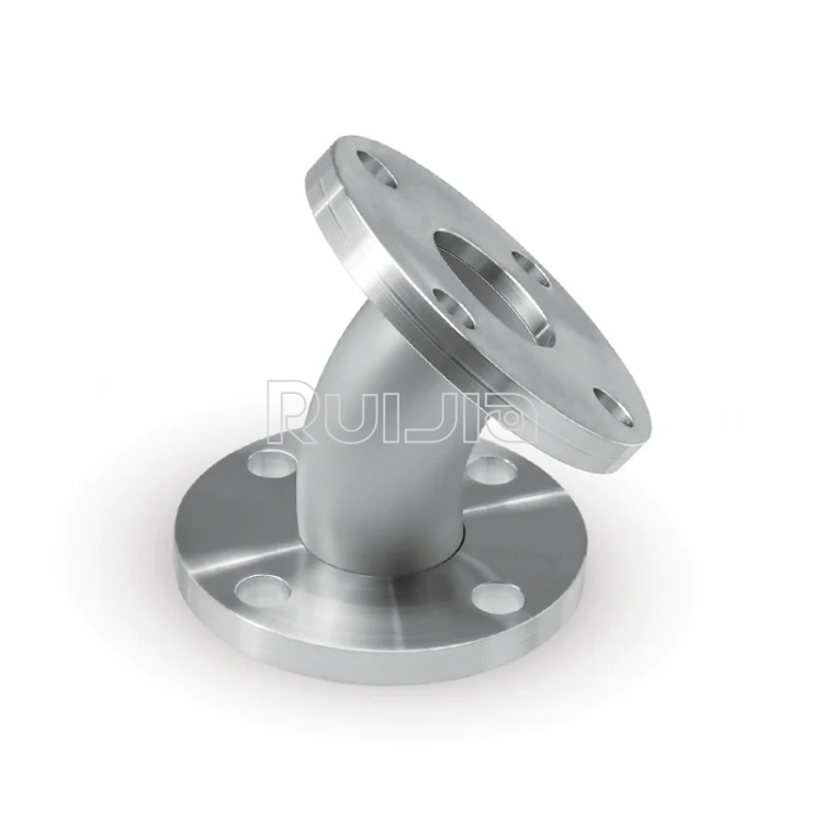
But an elbow also introduces a conductance loss. For viscous and transitional flow regimes, the extra turbulence inside a 90° bend can effectively lengthen the pipe run. In high-vacuum systems where every centimeter of path matters, a 45° elbow paired with a short straight section is often a smarter play than a single hard 90° — if you have the space. At the roughing line level, the difference is usually negligible, but it’s good practice to keep bends to the minimum your layout truly requires.
From a mechanical standpoint, elbows also act as a moment arm. A heavy valve or gauge hanging off an elbow that isn’t supported can slowly ovalize the O-ring groove or wear the clamp lip. A practical rule of thumb that seasoned technicians follow: if you can feel the assembly bounce when you tap it, add a bracket or swap to a tee with a blanked port so the weight sits on the centerline.
When ordering, pay attention to whether the elbow is formed from a single casting or fabricated from two flanges and a bent tube. Single-piece bodies remove one potential leak path (the weld) and generally offer smoother internal surfaces. If you are evaluating options for elbows that fit into a compact manifold, you can find detailed specifications for KF elbows and other modular shapes that list exact outer dimensions and weight — critical numbers when every millimeter counts inside a frame.
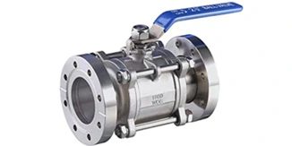
If an elbow is a turn, a tee is a decision: it splits a single line into two paths. The most common arrangement is an equal tee, with all three ports sharing the same nominal size — say, KF25 on all sides. You’ll see these used to connect a roughing valve, a vent valve, and a foreline trap to the same pump inlet, or to mount a thermocouple gauge directly in the pumping path.
A tee keeps the main run straight and takes the branch off at 90 degrees. This matters because the straight-through path preserves the original conductance better than a sharp turn does. When you’re planning a layout, put the highest-flow path on the straight ports and the lower-flow, intermittent line (like a purge gas inlet) on the branch. This small habit improves pump-down time without adding any cost.
Watch out for one recurring mistake: treating a tee as a structural support. A typical KF25 tee with a Pirani gauge and a small valve on the branch can easily exceed two kilos cantilevered off the pump flange. The O-ring near the clamp takes that bending load and deforms slightly, producing a leak that only appears under vacuum and disappears when you remove the clamp to inspect. A simple bracket that holds the gauge body can eliminate that elusive leak entirely. For systems where multiple instruments must share a single pump port, a well-chosen vacuum plumbing layout can prevent this kind of chronic troubleshooting.
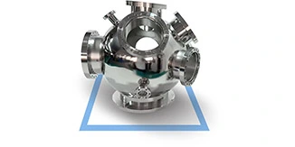
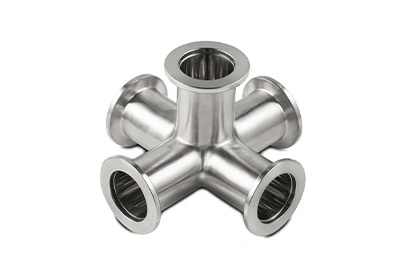
A cross is essentially two tees occupying the same coordinates. It offers four ports in a flat plane, making it the most connection-dense piece in the KF arsenal. You’ll find crosses used on top of turbomolecular pumps where you need to attach a gauge, a vent valve, and a residual gas analyzer simultaneously, or on chamber lids where multiple feedthroughs converge.
The obvious benefit is space savings. Replacing a chain of tees and elbows with one cross reduces the number of sealing surfaces — and therefore the number of places that can leak. Fewer clamps also mean less thermal mass if you’re baking the system. However, a cross imposes a conductance penalty on all four limbs that is slightly larger than a single tee’s because the flow can expand into the unused port. If one port remains unused, blank it with a proper KF blank flange and centering ring, not a homemade plate. The dead volume created by an unblanked port can act as a virtual leak, outgassing slowly and confusing your pressure readings for hours.
Alignment is especially finicky with crosses. Because four clamps must sit perfectly flat on the same plane, even a minor angular mismatch on one port stresses the O-rings on the other three. The habit of tightening clamps gradually in a star pattern — the same instinct you’d use when bolting down a flange on a larger ISO-F connection — pays dividends here.
If your design calls for multiple diagnostic tools on the same chamber port, you could chain a tee and an elbow together and live with the added leak points, or you could opt for a single cross. The latter approach keeps the system cleaner and easier to test. For those laying out a new manifold from scratch, browsing modular vacuum building blocks that illustrate port combinations can spark ideas for layouts you hadn’t considered.
| Situation | Recommended Fitting | Why |
| Change direction in a straight line | 90° or 45° Elbow | Simple, compact turn |
| Attach a gauge or vent to a main line | Equal Tee | Straight-through flow preserved |
| Need two branches close together | Cross | Fewer clamps, smaller footprint |
| Heavy component on a branch | Tee plus support bracket | Weight centered, less lever arm |
This table isn’t absolute — vacuum design often bends the rules — but it’s a starting point that can save a new builder from the classic mistake of putting a heavy right-angle valve on an unsupported elbow and then chasing a 10⁻⁶ mbar leak for a week.
Stainless steel 304 and 304L dominate for KF fittings. If your process involves corrosive gases or you need to bake above 150°C repeatedly, look for 316L and Viton O-rings instead of the standard NBR (Buna). The aluminum-bodied variants are tempting because of weight, but they gall easily if clamps are overtightened — a frequent issue when someone new to the lab hasn’t developed the “snug plus a quarter-turn” feel yet. If you run into a galling problem once, you’ll never forget it; swapping to stainless early avoids that education altogether.
O-ring lubrication is another quiet contributor to seal life. A thin film of vacuum-grade grease (PFPE-based, not hydrocarbon) on the O-ring lets it slide into the centering ring groove without rolling or pinching. This one step can extend the cycle life of a frequently opened joint by a factor of three or more.
Off-the-shelf elbows, tees, and crosses cover 90% of laboratory and pilot-scale vacuum needs. But occasionally you need a custom combination — a tee with a reduced branch, or a cross where one port is angled at 45° to save height. In those cases, working with a supplier that can adapt standard KF flanges and fittings into semi-custom geometries shortens lead time without pushing you into fully bespoke pricing. If you are curious about what a tailored set of KF connection solutions looks like for a chamber rebuild, Ruijia’s team regularly helps labs convert napkin sketches into clean, leak-tight assemblies.
Key Takeaways
Choose your fitting geometry based on flow path first, space second. Conduction is physics; cramped racks are just logistics.
Support any branch that weighs more than a small gauge — ideally with a bracket that bolts to a frame member.
Fewer seals mean fewer leaks. A cross that replaces a tee-and-elbow tangle is almost always worth the small extra conductance hit.
Grease your O-rings, tighten in a star pattern, and treat clamp lips as wear surfaces.
Understanding these three workhorse fittings turns vacuum system assembly from a guess into a deliberate, repeatable process. When you can glance at a chamber and instantly know whether an elbow or a tee belongs at the pump throat, the number of times you’ll find yourself re-tightening clamps at midnight drops dramatically. And for those moments when you need to explore dimensions, materials, or custom port configurations before cutting metal, you can always explore Ruijia’s complete range of KF connection solutions to see what’s possible off the shelf and what might need a bit of engineering.
ISO 2861:2020, Vacuum technology — Quick-release couplings — Dimensions.
O’Hanlon, J.F. A User’s Guide to Vacuum Technology, 3rd ed., Wiley, 2003.
Leybold GmbH, Fundamentals of Vacuum Technology, catalog 199-90.
Disclaimer: This article is for informational purposes only. Always follow your equipment manufacturer’s guidelines and local safety regulations when designing or modifying vacuum systems.
|
Temperature |
-26˚C to 200˚C |
|
Working Pressure |
Vacuum~atmosphere pressure |
|
Helium Leak Test |
1×10 -9 Pa・m³/sec or less |
|
Temperature |
-26˚C to 200˚C |
|
Working Pressure |
Vacuum~atmosphere pressure |
|
Helium Leak Test |
1×10 -9 Pa・m³/sec or less |
|
Temperature |
-26˚C to 200˚C |
|
Working Pressure |
Vacuum~atmosphere pressure |
|
Helium Leak Test |
1×10 -9 Pa・m³/sec or less |
Rich stock, fast delivery
Quick response within 24h
Quality assurance
Accessory replacement
GET A QUOTE