Determining adequate tightening torque for ISO-KF clamp connections, with size-based reference ranges and practical “enough” criteria.


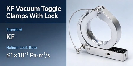
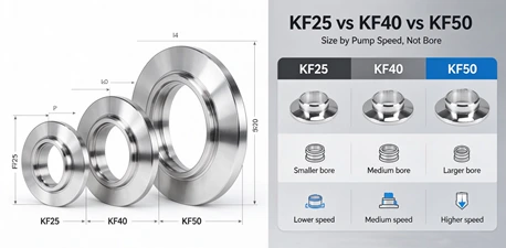
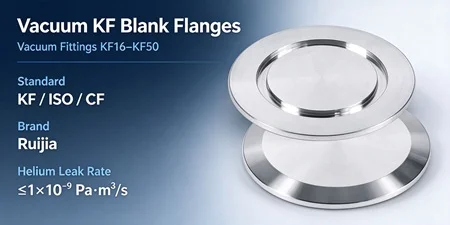
Elbows, tees, and cross pieces allow vacuum piping to change direction, branch, or combine, but each added fitting introduces a pressure drop and a potential leak point. The two factors that matter most are the fitting's internal geometry and the quality of the seal at each connection. This guide explains how these quick-fit components affect conductance, how to install them correctly, and what to check before final assembly.
In a vacuum system, every component between the chamber and the pump adds resistance to gas flow. That resistance is called flow impedance, and its inverse — the ability to pass gas — is called conductance. A straight length of tube has the highest conductance for a given bore size. When you insert an elbow, the gas must change direction; when you insert a tee or cross, the gas encounters a branch or an obstruction in the flow path.
The practical consequence is straightforward: a system with several elbows and tees between the chamber and the pump may reach a lower base pressure than the same system with straight tubing, even if the pump itself is unchanged. This does not mean elbows or tees should be avoided — they are necessary for routing. It means the layout should be planned with conductance in mind, and the fittings themselves should be selected and installed correctly.
A 90° elbow is the most common directional fitting in a quick-connect vacuum line. It allows the piping to turn without additional welded joints, which is especially useful in modular systems where components are frequently reconfigured.
The conductance penalty of an elbow depends on its internal radius. A long-radius elbow provides a smoother transition and generally produces less turbulence than a short-radius elbow of the same bore. In practice, many standard KF elbows have a relatively tight bend radius. For systems operating near the pump's ultimate pressure limit, using a long-radius elbow or a pair of 45° elbows can reduce the pressure drop compared with a single tight 90° bend.
Another consideration is rotational orientation. A KF elbow's clamp connection allows the fitting to rotate before tightening. This means the outlet can be aimed in any direction around the flange axis. When planning the routing, set the elbow's orientation before final clamp tightening — attempting to rotate a partially tightened KF joint can damage the centering ring or displace the O-ring.
If you need to review the available KF fitting configurations and sizes, the KF fittings category page lists the full range of elbows, tees, and crosses.
A tee introduces a branch into the flow path. A cross piece extends this to two branches. Both are essential for connecting gauges, vents, or secondary pump lines, but each branch represents an additional path for gas to travel — and an additional opening that must be sealed if not in use.
The flow behavior at a tee depends on how the branch is used:
Active branch (flow through): The tee acts as a junction where the gas stream splits or combines. Conductance through the main run is reduced compared to straight tubing because the branch opening disrupts the smooth flow path.
Blanked branch: If the branch port is sealed with a blank flange, the tee behaves more like a straight section with a small cavity. The conductance penalty is lower than an active branch but still present.
Gauge or sensor port: A tee used to mount a vacuum gauge adds a dead-end volume. This is generally acceptable for pressure measurement, but a long or large-diameter branch can act as a virtual leak during pump-down if it traps gas.
Cross pieces amplify these effects because they present two branch openings. In systems where conductance is critical, consider whether a cross can be replaced by two tees or by a manifold arrangement that places branch points closer to the chamber.
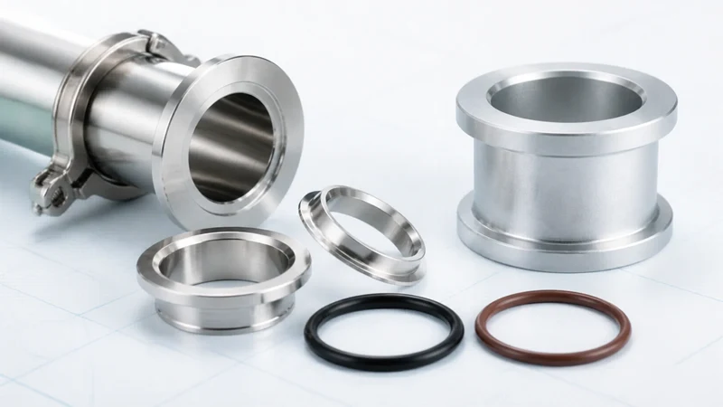
Correct installation of quick-fit fittings follows the same basic sequence as any KF joint, with a few additional checks specific to branched and directional components.
Step 1 — Verify interface dimensions before assembly. Confirm that the flange designation (KF16, KF25, KF40, KF50) matches on both sides of the joint, and that the tube outside diameter of the fitting matches the tube it will connect to. KF flange size and tube outside diameter are related but not always identical, particularly when components come from different manufacturers or follow different regional tube systems.
Step 2 — Inspect the sealing surfaces and O-ring. Check the flange faces for scratches, burrs, or embedded particles. Inspect the centering ring and O-ring for cuts, deformation, or signs of previous compression set. A damaged O-ring is the most common cause of leaks at quick-fit joints.
Step 3 — Set orientation before tightening. For elbows, tees, and crosses, the rotational position of the fitting determines the direction of the branch or outlet. Rotate the fitting to the desired position while the clamp is loose. Do not force rotation after the clamp has been tightened — this can displace the centering ring and compromise the seal.
Step 4 — Close the clamp and verify the seal. Use the correct clamp size for the flange designation. Tighten the wingnut by hand until the clamp is snug; the clamp's angled geometry is designed to apply even compression without requiring excessive force. The required seating torque for KF connections is typically in the range of 3.2 N·m (28 in·lb), though this should be confirmed against the component specification.
Step 5 — Perform a leak check before operation. Apply the project's agreed leak-check procedure — helium leak detection, pressure decay, or another approved method — before bringing the system into service. For branched fittings, pay particular attention to the branch port seal if it is blanked.
| Mistake | Consequence | Correct Approach |
| Over-tightening the clamp on a tee or cross | Flange distortion or cracking | Tighten by hand until snug; do not use tools to force the wingnut |
| Rotating the fitting after clamp is tight | Displaced centering ring; leak path | Set orientation before final tightening |
| Mismatched flange size on a branch port | Cannot seal; forced assembly damages faces | Verify all flange designations before assembly |
| Leaving a branch port open or loosely capped | Major leak; system cannot reach target vacuum | Blank-off unused ports with the correct blank flange and seal |
| Using a long branch tee for a pressure gauge | Dead volume traps gas; slow pump-down | Use the shortest branch that accommodates the gauge |
When planning a vacuum line that includes multiple quick-fit fittings, keep these principles in mind:
Minimize the number of elbows. Each 90° elbow adds impedance. If the routing allows, replace two 45° elbows with a single long-radius bend, or rearrange the layout to reduce total direction changes.
Place branch points close to the chamber. A tee or cross near the pump inlet exposes the branch to higher gas flow rates. A branch near the chamber sees lower flow and has less impact on overall conductance.
Use the largest bore that fits the application. Conductance scales strongly with internal diameter. If the system has the space and the pump has the capacity, stepping up to the next KF size for the main run can offset the impedance added by fittings.
Avoid sharp transitions. A tee with a small branch on a large main run creates an abrupt change in cross-section. This is sometimes unavoidable, but the transition should be as gradual as the available fittings allow.
If your application involves frequent reconfiguration or a mix of KF and ISO components, the available adapter configurations may offer a routing solution that reduces fitting count.
Can I use a KF tee with only two ports connected?
Yes. A KF tee can function as a straight-through connection if the third port is properly blanked with a blank flange and centering ring assembly. The blanked port adds a small cavity to the flow path but does not prevent operation. Ensure the blank-off is leak-tight before pump-down.
Does the orientation of an elbow affect its conductance?
The internal geometry of the elbow determines its conductance; the external rotational orientation does not change the flow path through the fitting. However, orientation affects how the connected tubing is routed, which in turn affects the overall system conductance. A poorly oriented elbow may force additional bends downstream.
What is the difference between a KF cross and two KF tees?
A single cross piece occupies less linear space than two tees installed in series. However, a cross concentrates two branch openings at one point, which can create a more complex flow disruption. Two tees spread the branch points apart, which may be preferable if one branch is used for a gauge and the other for a vent line.
How do I know if a KF fitting is leaking?
Common indicators include the system failing to reach its target base pressure, a rising pressure reading after isolation, or a response from a helium leak detector. For branch fittings, check the blank-off port seal first — it is a common leak point that is sometimes overlooked.
Can I mix KF fitting sizes in one vacuum line?
You can connect different KF sizes using reducing adapters, but you should not force a mismatched flange into a clamp. Forcing a KF16 flange into a KF25 clamp, for example, can damage the sealing face and will not produce a reliable seal. Use the correct adapter or reducer for size transitions.
How tight should the clamp be on a KF elbow or tee?
The clamp should be tightened by hand until it is snug. The angled surfaces of the KF flanges and the clamp geometry apply the correct compression when the clamp is fully closed by hand. Additional force with tools is not required and can distort the flange or damage the centering ring.
Elbows, tees, and cross pieces are not passive components in a vacuum system — they shape the flow path and determine how efficiently gas travels from the chamber to the pump. The key decisions are: how many direction changes the routing requires, where branch points are placed, and whether each joint is assembled with the correct orientation and seal.
The most common errors are procedural: rotating a fitting after tightening the clamp, leaving a branch port inadequately sealed, or over-tightening the clamp in the belief that more force produces a better seal. Avoiding these errors costs nothing and prevents the majority of installation-related leaks.
When the application involves corrosive media, elevated temperatures, or ultra-high vacuum targets, the fitting material and seal selection require technical confirmation beyond what a standard KF configuration provides. Review the available KF fitting configurations and sealing options, or discuss the material and process requirements with the supplier before finalizing the bill of materials.
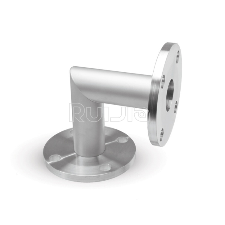
|
Temperature |
-26˚C to 200˚C |
|
Working Pressure |
Vacuum~atmosphere pressure |
|
Helium Leak Test |
1×10 -9 Pa・m³/sec or less |
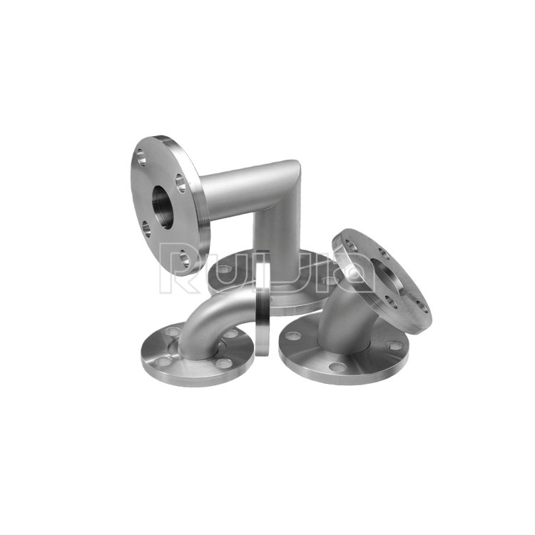
|
Temperature |
-26˚C to 200˚C |
|
Working Pressure |
Vacuum~atmosphere pressure |
|
Helium Leak Test |
1×10 -9 Pa・m³/sec or less |
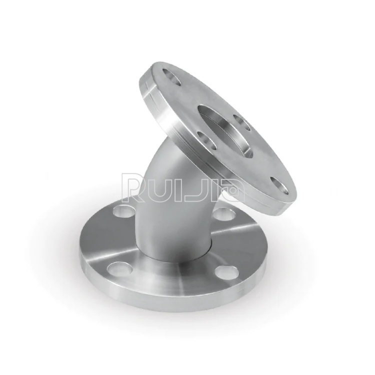
|
Temperature |
-26˚C to 200˚C |
|
Working Pressure |
Vacuum~atmosphere pressure |
|
Helium Leak Test |
1×10 -9 Pa・m³/sec or less |
Rich stock, fast delivery
Quick response within 24h
Quality assurance
Accessory replacement
GET A QUOTE