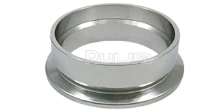
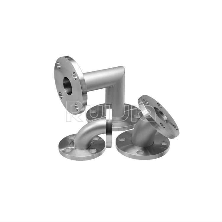
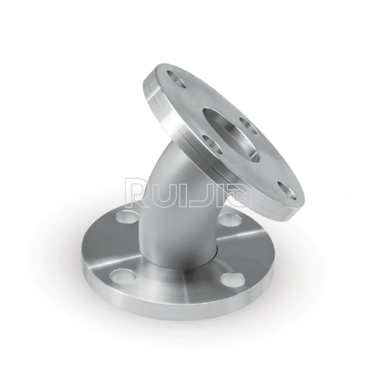
The term "KF" originates from the German Klein Flansche, translating to "small flange" in English. These flanges feature a 15-degree chamfer on the rear surface and are joined via tapered circular clamps. Manufactured to DIN 28403/ISO 2861 and Pneurop standards, KF flanges are "sexless"—both mating surfaces are identical, and no O-ring grooves are machined into the flange bodies. In contrast to CF flanges, KF types are prized for their simplicity and ease of use, while CF flanges are typically reserved for high-vacuum applications requiring metal seals.
Flange sizing is based on the largest nominal inner diameter (I.D.) of tubing (in millimeters) that can be welded to it. For example, a KF25 flange has a 25 mm through-hole (≈1 inch). In the U.S., welded tubing often uses nominal inch sizes, which approximate but do not precisely match metric designations, whereas components manufactured outside the U.S. generally employ metric I.D. tubing.
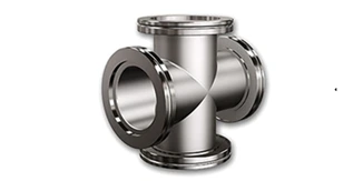
Standard KF sizes include KF10, KF16, KF25, KF40, and KF50; KF20 and KF32 are less common. This flange system is also known by aliases such as NW, QF, DIN, and ISO-KF, referring to identical designs.
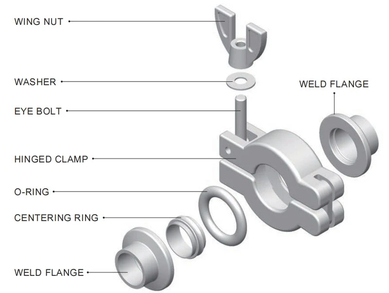
Operational Principle
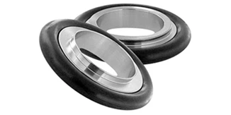
A centering ring with an O-ring is positioned between flanges, which are aligned and brought together. A wing nut clamp (or optional chain clamp) is fastened around the flange faces; tightening the wing nut squeezes the flanges, compressing the O-ring to form a seal.
Cross-Comparison of Flange Types
These flanges operate in pressure ranges from atmospheric to as low as 1×10⁻⁸ Torr (mbar). The operational and bakeout temperature range depends on O-ring material:
FKM (Viton-A): The most common choice, suitable for 0–180°C (32–356°F), with short-term exposure to -26–204°C (-15–400°F). Leakage/permeability with FKM is 1×10⁻⁹ std cc/sec (Helium).
Material Specifications
Primary material: 304/304L stainless steel.
Alternatives: 316L, 316LN stainless steel, and 6061 aluminum.